
User's Guide

PT7682W/PT7686W-SAOPTC0 HDK User Guide
PTCOM Technology Inc. www.ptcom.com.tw Proprietary & Confidential Information 9
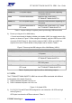
Jumper Usage Comments
J2002(1-2) 3.3V power supply Use micro-USB connector supporting
3.3V power source
J2004 Current measurement Measures the current flow in
PT7682W/PT7686W-SAOPTC0
J2003(1-2) RTC3V3 power supply Use micro-USB connector supporting RTC
3V3 power
J2007 Current measurement in
RTC mode
Measures the current flow in RTC mode
for PT7682W/PT7686W-SAOPTC0
Table 1. Jumper settings for system power input through USB connection
2). Power up using an AA or AAA battery.
• Connect an external AA battery to battery pin header (J2001) to supply power to the
system, as shown in Figure 5. When using an AA battery, plug the USB to micro-USB
connector CON5 (Figure 2). Note, that the jumpers J2003, J2004, and J2007 are
required to be set on. More details on the jumpers can be found in Table 2.
Figure 5. Power up the HDK using an AA or AAA Battery (J2001)
Jumper Usage Comments
J2002(2-3) 3.3V power supply Use AA or AAA battery source supporting
3.3V power
J2004 Current measurement Measures the current flow in
PT7682W/PT7686W-SAOPTC0
J2003(2-3) RTC3V3 power supply Use AA or AAA battery source supporting
RTC 3V3 power
J2007 Current measurement in
RTC mode
Measures the current flow in RTC mode
for PT7682W/PT7686W-SAOPTC0
Table 2. System power input from AA or AAA battery jumpers
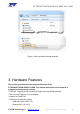
4.3 LEDs
The PT7682W/PT7686W-SAOPTC0 HDK has onboard LEDs associated with different
functionalities of the board (Figure 6).
1). D2002 indicates the power rail 5V is on.
2). D2001 indicates the power rail 3.3V is on.
Figure 6. On-board LEDs
3). D1, D2, D3, D4, and D5 are LEDs assigned for user interaction. All LEDs are high
active (Figure 6).
GPIO pins to activate the LEDs are shown in Table 3.