
User's Guide


PT7682W/PT7686W-SAOPTC0 HDK User Guide
PTCOM Technology Inc. www.ptcom.com.tw Proprietary & Confidential Information 10
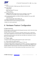
LED GPIO
D1 GPIO11
D2 GPIO12
D3 GPIO13
D4 GPIO14
D5 GPIO15
Table 3. GPIO pins to activate the LEDs
4.4 Buttons
The PT7682W/PT7686W-SAOPTC0 HDK is equipped with buttons with the following
functionality. The push buttons are shown in Figure 2.
1). System reset button (S2001) resets the MT7682 HDK.
2). External interrupt button (S2005). Users can configure GPIO0 as an external interrupt
pin. Press the button to wake up the system from the sleep mode.
3). External interrupt button (S2006). To enter RETENTION mode is software configurable
and to exit, use RTC timer or EINT.
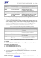
4.5 Extension Connectors
The PT7682W/PT7686W-SAOPTC0 HDK provides similar pin-out extension connectors
(J2101 and J2103) for various sensor and device connectivity, as shown in Figure 2 and
described in Table 4.
The board has 14 GPIOs multiplexed with other interfaces. Depending on the use case,
user can configure each I/O functionality.
Connector Pin
Number
Signal Name Connector Pin
Number
Signal Name
J2101.1 GPIO20 J2103.1 GPIO0
J2101.2 GPIO19 J2103.2 GPIO1
J2101.3 GPIO18 J2103.3 GPIO2
J2101.4 GPIO17 J2103.4 GPIO3
J2101.5 GPIO16 J2103.5 GPIO4
J2101.6 GPIO15 J2103.6 GPIO5
J2101.7 GPIO14 J2103.7 GPIO6
J2101.8 GPIO13 J2103.8 GPIO7
J2101.9 GPIO12 J2103.9 GPIO8
J2101.10 GPIO11 J2103.10 GPIO9
J2103.11 GPIO10
Table 4. GPIO pin multi-function definition and pin-out extension connectors
*Note*