
User's Guide


PT7682W/PT7686W-SAOPTC0 HDK User Guide
PTCOM Technology Inc. www.ptcom.com.tw Proprietary & Confidential Information 11
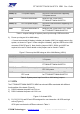
Use the GPIO8 and GPIO9 pins as I2C0, add pull-up resistors on the HDK or on the I2C0
daughterboard. To add pull-up resistors on the HDK, refer to the resistor locations in Figure
7. The location of R2101 is for adding the pull-up resistor for I2C0_SDA (GPIO9). The
location of R2102 is for adding the pull-up resistor for I2C0_CLK (GPIO8).
Figure 7. Locations of I2C pull-up resistors
4.6 RTC
The PT7682W/PT7686W-SAOPTC0 HDK features an RTC module. The clock source
operates at 32.768kHz crystal oscillator or an external clock source. The RTC has built-in
accurate timer to wake up the system when the user-defined timer expires. The RTC uses a
different power source from the Power Management Unit (PMU). In hibernate or sleep mode,
the PMU is turned off while the RTC module remains powered on. The RTC module only
consumes 3µA in hibernate mode. The RTC has a dedicated PMU control pin
PMU_EN_RTC (pin 14) used to turn the power on when the RTC timer expires and turn the
power off when it intends to enter the hibernate mode.
4.7 RF connections
By default, the board ships with RF signals routed to the on-board chip antenna. An
on-board U.FL, a conductive test component, (I-PEX) connector only available on
PT7682W/PT7686W-SAOPTC0-SC version.
4.8 CMSIS-DAP Firmware update procedure
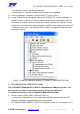
The latest firmware from OpenSDA platform can be downloaded from the mbed official
website. To update the binary firmware of CMSIS-DAP, press and hold the S2001, then
plug-in the USB cable to CON3001, release the button S2001 once the mass storage is
shown, and then drag and drop in the binary code. After the mass storage disappears, keep
the power connected for 10 seconds, and then reboot the system again to finish the
firmware update.
*Note*
Before you start to update CMSIS-DAP firmware via CON3001, please remember to confirm
the Jumpers J2107 and J2108 are put on 2 and 3 pin.