
User's Guide

PT7682W/PT7686W-SAOPTC0 HDK User Guide
PTCOM Technology Inc. www.ptcom.com.tw Proprietary & Confidential Information 3
1. Introduction
PT7682W/PT7686W-SAOPTC0 HDK for real-time operating system (RTOS) is a low-cost
and easy to use Internet of Things (IoT) development platform to design, prototype, evaluate
and implement IoT projects. The platform supports PT7682W/PT7686W-SAOPTC0
hardware development kit (HDK) by SAC. This user manual provides required knowledge
on features of the HDK, including the pins, communication interfaces, core microcontroller
unit (MCU) description, the networking capabilities and how to use them through the host
driver.
The HDK includes PT7682/86 stamp module enables rich connectivity features,
communication with cloud services and real-time control. The
PT7682W/PT7686W-SAOPTC0 HDK supports ARM mbed IoT Device Platform for more
convenient debugging and binary code download operations.
The following features are available:
• Mass storage device (MSD) programmer.
-- The PT7682W/PT7686W-SAOPTC0 HDK has three binary files for bootloader, Wi-Fi
connectivity and FreeRTOS. The MSD programmer enables to update the FreeRTOS binary
file only.
• Coresight Debug Access Port (CMSIS-DAP) debug interface.
-- A firmware debug interface similar to ST-link or J-link. It enables debugging a target
project or downloading a binary to the flash storage of the device.
• Virtual Serial Port.
-- Supports UART functionality, such as transferring log information from the HDK.
These features are used to download and debug a project on
PT7682W/PT7686W-SAOPTC0 HDK.
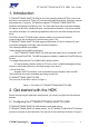
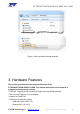
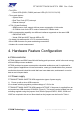
The front view of the HDK is shown in Figure 1.
Figure 1. Front View of PT7682W/PT7686W-SAOPTC0 HDK
2. Get started with the HDK
Before commencing the application development, you need to configure the development
platform.
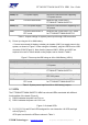
2.1 Configuring the PT7682W/PT7686W-SAOPTC0 HDK
PT7682W/PT7686W-SAOPTC0 HDK includes a main board and a
PT7682W/PT7686W-SAOPTC0 stamp module. The PT7682W/PT7686W-SAOPTC0 stamp
module is mounted on the main board. The top view of the main board is shown in Figure 2.