
User's Guide

PT7682W/PT7686W-SAOPTC0 HDK User Guide
PTCOM Technology Inc. www.ptcom.com.tw Proprietary & Confidential Information 4
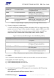
Figure 2. Jumpers and connectors on the PT7682W/PT7686W-SAOPTC0 HDK
The description of pins (Figure 2) and their functionality is provided below.
1). CON3001 is a USB connector to debug through UART, transmit and receive a signal
and supply power from the PC. The USB connectivity with the PC is supported by the
on-board MK20DX128VFM5.
i. Set the jumpers J2002, J2003, J2004 and J2007 on, if the board is powered by a
USB connector.
2). S2005 enables the external interrupt (configured at GPIO0), see section 4.4, “Buttons”,
for more details.
3). S2006 enables the external interrupt (Dedicate EINT input in RTC), see section 4.4,
“Buttons”, for more details.
4). Press S2001 to reset the system.
5). Wi-Fi Antenna is a PCB antenna. PT7682W/PT7686W-SAOPTC0 stamp module is by
default connected to the PCB antenna to transmit and receive RF signals.
The default configuration of the PT7682W/PT7686W-SAOPTC0 HDK supports the
following functionality:
1). Power supply. Attach a micro-USB connector to the CON3001.
2). Supports RTC interrupt.
3). Clock source — 32.768kHz source crystal clock for the RTC mode or external clock
operating on 32.768 kHz.
4). XTAL at 40MHz.
5). Supports RTC mode.
The hardware settings of the stamp module are shown below:
1). XTAL at 40MHz.
2). Clock source — 32.768kHz source crystal clock for the RTC mode or external clock
operating at 32.768kHz.
3). Supports RTC mode.
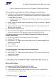
2.2 Installing the PT7682W/PT7686W-SAOPTC0 HDK drivers on
Microsoft Windows
To configure the PT7682W/PT7686W-SAOPTC0 HDK:
1). Connect the HDK to the computer using a micro-USB cable.
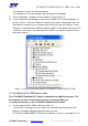
2). Download and install mbed Windows serial port driver from here. Open Windows
Control Panel then click System and: