
User's Guide

PT7682W/PT7686W-SAOPTC0 HDK User Guide
PTCOM Technology Inc. www.ptcom.com.tw Proprietary & Confidential Information 8
• Ten LEDs
--Power LEDs (D2001, D2002) and user LEDs (D1, D2, D3, D4, D5).
• Three push buttons
--System Reset.
--Real Time Clock (RTC) Interrupt.
--External Interrupt.
• XTAL (Crystal Oscillator)
--40MHz source clock support with low power consumption in idle mode.
--32.768kHz clock for the RTC mode or external 32.768kHz mode.
• USB re-enumeration capability: two different interfaces supported on the same USB.
--CMSIS-DAP USB.
--Virtual COM port UART through USB on PC.
• On-board chip antenna with U.FL for conducted testing.
• Micro USB connector for power and debug connections.
• Headers for current measurement.
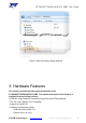
4. Hardware Feature Configuration
4.1 Microcontroller
MT7682 features an ARM Cortex-M4 with floating point processor, which is the most energy
efficient ARM processor available.
MT7682 provides low power consumption embedded architecture and it’s optimized for
various types of applications in home automation, smart grid, handheld devices, personal
medical devices and industrial control that have lower data rates, and transmit or receive
data on an infrequent basis.
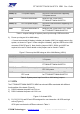
4.2 Power supply
PT7682W/PT7686W-SAOPTC0 HDK supports two types of power supply.
1). Power up with a micro-USB connector.
An on-board switching regulator provides voltage of 3.3V for the
PT7682W/PT7686W-SAOPTC0 HDK based on MT7682F, if the power is supplied from an
on-board micro-USB connector CON3001 (Figure 2). This supply can be isolated from the
switching regulator using the jumpers. Note, that the jumpers J2002, J2003, J2004 and
J2007 are required to be set on. More details on the jumpers can be found in Table 1.