PTZOptics 12x 3G-SDI (GEN 2) User Manual Model Nos: PT12X-SDI-GY-G2 & PT12X-SDI-WH-G2 V1.6 (English) Please check PTZOPTICS.com for the most up to date version of this document Rev 1.
Preface Thank you for using the HD Professional Video Conferencing Camera. This manual introduces the function, installation and operation of the HD camera. Prior to installation and usage, please read the manual thoroughly. Precautions This product can only be used in the specified conditions in order to avoid any damage to the camera: • Don’t subject the camera to rain or moisture. • Don’t remove the cover. Removal of the cover may result in an electric shock. In addition to voiding the warranty.
Table of Contents 1 Supplied Accessories ··································································································· 1 2 Notes ······················································································································ 1 3 Quick Start ··············································································································· 2 4 Features ·····························································································
Supplied Accessories When you unpack your camera, check that all the supplied accessories are included: ⚫ Camera ................................ 1 ⚫ AC Power Adaptor .............. 1 ⚫ Power Cord ........................... 1 ⚫ RS232 Cable ......................... 1 ⚫ IR Remote Controller ........... 1 ⚫ This User Manual ............... 1 ⚫ AAA Batteries.......................
Quick Start Step 1. Please check that all connections are correct before powering on the camera. Page 2 of 56 Rev 1.
Step 2. Set the system select switch for your desired video output resolution and frame rate. For many applications, setting 0 (1080p-60) will provide the best overall performance. For highest possible resolution, use setting 0 (1080p-60) or 6 (1080p-30), however your actual realized frame rate may be limited to a lower value than 60 fps by your software, hardware, and/or network connection. NOTE: After changing this dial, you need to restart the camera to see the effect. Turn the camera off then on.
Features 1. Supports simultaneous 3G-SDI, HDMI and IP network streaming up to 1080p-60. 2. Supports non-simultaneous CVBS (composite video) output via RCA connector (480i or 576i). 3. Includes Panasonic's high quality, 1/2.7 inch, 2.07 million effective pixels, HD CMOS sensor, which can produce a maximum 1920 x 1080 image with a high quality, maximum output frame rate of 60 fps (frames per second). 4. Ultra-high frame rate 60fps for HDMI and USB and up to 120fps for IP Streaming (120fps at 720p only). 5.
Product Specifications Model PT12X-SDI-GY-G2 and PT12X-SDI-WH-G2 Type PTZOptics 3G-SDI HD 1080p Color Video Camera (GEN 2) Features 1080p-60/50/30/25/59.94*/29.97* 1080i-60/50/59.94* 720p-60/50/59.94* Video System CVBS: 576i, 480i *Broadcast frame rates are considered BETA features and may not be supported by all platforms Sensor Panasonic 1/2.7", CMOS, Total Pixels: 2.12M, Effective Pixels: 2.07M Scanning Mode Progressive Lens 12x; f3.5mm – 42.3mm; F1.8 - F2.
1x RJ45 IP 10/100/1000 Ethernet Port SD Output 1x CVBS: 3.5mm jack, 1Vp-p, 75Ω (requires adapter cable to connect to standard RCA input) Network Interface and Output 1x RJ45: 10M/100M/1000M Adaptive Ethernet port Audio Input 1-ch 3.
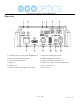
Main Unit 1. Audio LINE IN Interface (IP Stream & HDMI only) 7. Network (IP streaming and control) 2. CVBS (composite video SD) Interface 8. HDMI 1.3 (Digital Video Output) 3. System select dial (resolution) 9. 3G-SDI (Serial Digital Video Output) 4. RS485 jack 10. USB 2.0 (*no video out* Future - USB Storage) 5. RS232 IN jack 11. DC 12V power jack 6. RS232 OUT jack (pass through for daisy chain) 12. Power switch Page 7 of 56 Rev 1.
IR Remote Controller 1. Standby Button Press this button to enter standby mode. Press it again to enter normal mode. NOTE: Power consumption in standby mode is approximately half of the normal mode. 2. Position Buttons To set preset or call preset. 3. * Button For multiple function. 4&13.
. Multiple Function Buttons Function 1. Set camera IR address Press 3 keys contiguously can set camera IR address as follow: [*] + [#] + [F1]: Address 1 [*] + [#] + [F2]: Address 2 [*] + [#] + [F3]: Address 3 [*] + [#] + [F4]: Address 4 Function 2. Image freezing function Press [F4] to start the freeze function. The word "Freeze" displays on the upper left corner. After five seconds, the display disappears automatically (though the freeze feature continues).
Using the IR Remote Controller 2. Zoom Control When the camera is operational, you can use the remote controller to perform panning, tilting, zooming and focusing, as well as store and call back preset positions. Button Instructions: 1. In these instructions, ‘press the button’ means to press and release. A special note will be given if holding a button down for more than one second is required. 2. When a button-combination is required, do it in sequence (not simultaneously).
4. BACKLIGHT. L/R SET and P/T RST Controls 6. Presets - Setting and Clearing Reverse Pan controls direction: Press and hold [L/R SET] button while pressing [1] aka [STD] button for normal pan controls. Press and hold [L/R SET] button while pressing [2] aka [REV] button for reversed pan controls. Backlight Compensation Control: Press [BACKLIGHT] button to enable backlight compensation. Press it again to disable backlight compensation.
7. Recalling Presets 9. Camera IR Address Set Press 3 buttons in the sequence shown below to set/change the camera’s IR address. This allows up to 4 cameras to be controlled from the same IR remote control. Be sure that only one camera is picking up the IR signal when you perform this function. If multiple cameras Pressing any of the numeric buttons [0-9] directly will receive the command, they will all change to the new recall a stored preset position and settings. address.
Dimensional Drawings (mm) Page 13 of 56 Rev 1.
RS-232 Interface Camera PC/Controller DB-9 1.DTR 1.CD 2.DSR 2.RXD 3.TXD 3.TXD 4.GND 4.DTR 5.RXD 5.GND 6.GND 6.DSR 7.IR OUT 7.RTS 8.NC 8.CTS 9.RI 1st For Control Daisy Chain Camera 2nd Camera Mini DIN No. Function 1 DTR 2 DSR 1.DTR 1.DTR 3 TXD 2.DSR 2.DSR 4 GND 3.TXD 3.TXD 5 RXD 4.GND 4.GND 5.RXD 5.RXD 6 GND 6.GND 6.GND 7 IR OUT 7.IR OUT 7.NC 8 NC 8.NC 8.NC Page 14 of 56 Rev 1.
Serial Communication Control In default working mode, the camera is able to connect to a VISCA controller with an RS232C serial interface. ➢ RS232 Communication Control The camera can be controlled via RS232. The parameters of RS232C are as follows: Baud rate: 2400, 4800 or 9600 bps. ➢ Start bit: 1 bit. Data bit: 8 bits. Stop bit: 1 bit. Parity bit: none. RS485 Communication Control The camera can be controlled via RS485, Half-duplex mode, with support for VISCA, Pelco-D or Pelco-P protocol.
VISCA Command List Part 1: Camera-Issued Messages ACK/Completion Message Function Command ACK/Completion Messages Command Packet z0 4y FF ACK (y: Socket No.) Completion z0 5y FF (y: Socket No.) Comments Returned when the command is accepted. Returned when the command has been executed.
Part 2: Camera Control Commands Command Function Command Packet Comments AddressSet Broadcast 88 30 01 FF Address setting IF_Clear Broadcast 88 01 00 01 FF I/F Clear On 8x 01 04 00 02 FF Off 8x 01 04 00 03 FF Stop 8x 01 04 07 00 FF Tele(Standard) 8x 01 04 07 02 FF Wide(Standard) 8x 01 04 07 03 FF Tele(Variable) 8x 01 04 07 2p FF Wide(Variable) 8x 01 04 07 3p FF Direct 8x 01 04 47 0p 0q 0r 0s FF Stop 8x 01 04 08 00 FF Far(Standard) 8x 01 04 08 02 FF Near(Standard) 8x 01 04 08
Full Auto 8x 01 04 39 00 FF Automatic Exposure mode Manual 8x 01 04 39 03 FF Manual Control mode Shutter priority 8x 01 04 39 0A FF Shutter Priority Automatic Exposure mode Iris priority 8x 01 04 39 0B FF Iris Priority Automatic Exposure mode Bright 8x 01 04 39 0D FF Bright Mode(Manual control) AutoSlowShutterLimit 8x 01 04 2A 0p 00 FF Reset 8x 01 04 0B 00 FF Up 8x 01 04 0B 02 FF Down 8x 01 04 0B 03 FF Direct 8x 01 04 4B 00 00 0p 0q FF Reset 8x 01 04 0C 00 FF Up 8x 01 04 0C 02 FF
Manual 8x 01 04 05 02 FF Reset 8x 01 04 02 00 FF CAM_Aperture(sharpn Up 8x 01 04 02 02 FF ess) Down 8x 01 04 02 03 FF Direct 8x 01 04 42 00 00 0p 0q FF Off 8x 01 04 63 00 FF B&W 8x 01 04 63 04 FF Reset 8x 01 04 3F 00 pp FF Set 8x 01 04 3F 01 pp FF Recall 8x 01 04 3F 02 pp FF On 8x 01 04 61 02 FF Off 8x 01 04 61 03 FF On 8x 01 04 66 02 FF Off 8x 01 04 66 03 FF CAM_RegisterValue - 8x 01 04 24 mn 0p 0q FF CAM_ColorGain Diret 8x 01 04 49 00 00 00 0p FF p: Color Gain setting 0
High 8x 01 04 58 01 FF Normal 8x 01 04 58 02 FF Low 8x 01 04 58 03 FF CAM_SettingReset Reset 8x 01 04 A0 10 FF Reset Factory Setting CAM_Brightness Direct 8x 01 04 A1 00 00 0p 0q FF pq: Brightness Position CAM_Contrast Direct 8x 01 04 A2 00 00 0p 0q FF pq: Contrast Position Off 8x 01 04 A4 00 FF Flip-H 8x 01 04 A4 01 FF Flip-V 8x 01 04 A4 02 FF Flip-HV 8x 01 04 A4 03 FF CAM_SettingSave Save 8x 01 04 A5 10 FF Save Current Setting CAM_Iridix Direct 8x 01 04 A7 00 00 0p 0q FF p
CAM_BGainInq CAM_AEModeInq 8x 09 04 44 FF 8x 09 04 39 FF y0 50 00 00 0p 0q FF pq: B Gain y0 50 00 FF Full Auto y0 50 03 FF Manual y0 50 0A FF Shutter priority y0 50 0B FF Iris priority y0 50 0D FF Bright CAM_ShutterPosInq 8x 09 04 4A FF y0 50 00 00 0p 0q FF pq: Shutter Position CAM_IrisPosInq 8x 09 04 4B FF y0 50 00 00 0p 0q FF pq: Iris Position CAM_BrightPosInq 8x 09 04 4D FF y0 50 00 00 0p 0q FF pq: Bright Position y0 50 02 FF On y0 50 03 FF Off y0 50 00 00 0p 0q FF pq: Ex
CAM_IDInq 8x 09 04 22 FF y0 50 0p 0q 0r 0s FF pqrs: Camera ID ab: Factory Code(00: VHD, 01:MR, 08:T) cd: Hardware Version mnpq: ARM Version CAM_VersionInq 8x 09 00 02 FF y0 50 ab cd rstu: FPGA Version mn pq rs tu vw FF vw: Camera model 01: C Type 02: M Type 03: S Type VideoSystemInq IR_Receive 8x 09 06 23 FF 8x 09 06 11 FF Pan-tiltPosInq 8x 09 06 12 FF 8x 09 00 03 FF CAM_DateInq 8x 09 00 04 FF CAM_ModeInq 8x 09 04 A6 FF CAM_GainLimitInq 1920x1080i60 y0 50 01 FF 1920x1080p30 y0 50 02
CAM_DHotPixelInq CAM_AFSensitivityInq 8x 09 04 56 FF 8x 09 04 58 FF y0 50 0q FF p: Dynamic Hot Pixel Setting (0: 0ff, level 1 to 6) y0 50 01 FF High y0 50 02 FF Normal y0 50 03 FF Low CAM_BrightnessInq 8x 09 04 A1 FF y0 50 00 00 0p 0q FF pq: Brightness Position CAM_ContrastInq 8x 09 04 A2 FF y0 50 00 00 0p 0q FF pq: Contrast Position y0 50 00 FF Off y0 50 01 FF Flip-H y0 50 02 FF Flip-V y0 50 03 FF Flip-HV y0 50 00 00 0p 0q FF pq: Iridix Position y0 50 00 FF Top y0 50 01 FF
pp: R_Gain qq: B_Gain r: WB Mode s: Aperture CAM_CameraBlockIn q 8x 09 7E 7E 01 FF y0 50 0p 0p 0q 0q 0r 0s tt 0u vv ww 00 xx 0z FF tt: AE Mode u.bit2: Back Light u.bit1: Exposure Comp. vv: Shutter Position ww: Iris Position xx: Bright Position z: Exposure Comp. Position CAM_OtherBlockInq 8x 09 7E 7E 02 FF y0 50 0p 0q 00 0r 00 00 00 00 00 00 00 00 00 FF p.bit0: Power 1:On, 0:Off q.bit2: LR Reverse 1:On, 0:Off r.bit3~0: Picture Effect Mode p: AF sensitivity q.
Part 4: VISCA over IP Command List Command CAM_Zoom CAM_Focus CAM_WB CAM_RGain CAM_BGain CAM_AE Function Command Packet Comments Stop 81 01 04 07 00 FF Tele (Standard) 81 01 04 07 02 FF Wide (Standard) 81 01 04 07 03 FF Tele (Variable) 81 01 04 07 2p FF Wide (Variable) 81 01 04 07 3p FF Direct 81 01 04 47 p q r s FF Stop 81 01 04 08 00 FF Far (Standard) 81 01 04 08 02 FF Near (Standard) 81 01 04 08 03 FF Far (Variable) 81 01 04 08 2p FF Near (Variable) 81 01 04 08 3p FF Direc
CAM_Iris CAM_Shutter CAM_Backlight CAM_Flicker CAM_PictureEffect CAM_Memory Preset Recall Speed CAM_LR_Reverse CAM_PictureFlip Pan Tilt Drive Reset 81 01 04 0B 00 FF Up 81 01 04 0B 02 FF Down 81 01 04 0B 03 FF Direct 81 01 04 4B 00 00 p q FF pq: Iris Position Reset 81 01 04 0A 00 FF Default Shutter Setting Up 81 01 04 0A 02 FF Down 81 01 04 0A 03 FF Direct 81 01 04 4A 00 00 p q FF On 81 01 04 33 02 FF Off 81 01 04 33 03 FF - 81 01 04 23 0p FF Off 81 01 04 63 00 FF B&W 81 01
CAM-Flip CAM_SettingSave CAM_AWBSensitivity CAM_AFZone CAM_ColorHue OSD_Control Off 81 01 04 A4 00 FF Flip-H 81 01 04 A4 01 FF Flip-V 81 01 04 A4 02 FF Flip-HV 81 01 04 A4 03 FF Save 81 01 04 A5 10 FF Save Current Setting High 81 01 04 A9 00 FF High Normal 81 01 04 A9 01 FF Normal Low 81 01 04 A9 02 FF Low Top 81 01 04 AA 00 FF Center 81 01 04 AA 01 FF Bottom 81 01 04 AA 02 FF Direct 81 01 04 4F 00 00 00 0p FF Single Command For Video Flip AF Zone priority select p: Color
90 50 0B FF Iris Priority (AAE) 90 50 0D FF Bright CAM_ShutterPosInq 81 09 04 4A FF 90 50 00 00 0p 0q FF pq: Shutter Position CAM_IrisPosInq 81 09 04 4B FF 90 50 00 00 0p 0q FF pq: Iris Position CAM_BrightPosInq 81 09 04 4D FF 90 50 00 00 0p 0q FF pq: Bright Position 90 50 02 FF On CAM_ExpCompModeInq 81 09 04 3E FF 90 50 03 FF Off 90 50 00 00 0p 0q FF pq: ExpComp Position 90 50 02 FF On 90 50 03 FF Off 90 50 02 FF Auto Noise 2D 90 50 03 FF Manual Noise 2D CAM_ExpCompPosInq 81
CAM_PanTiltPosInq CAM_GainLimitInq 90 50 0w 0w 0w 0w wwww: Pan Position 0z 0z 0z 0z FF zzzz: Tilt Position 90 50 0q FF p: Gain Limit 90 50 00 FF Off 90 50 01 FF Flip-H 90 50 02 FF Flip-V 90 50 03 FF Flip-HV 90 50 00 FF Top 90 50 01 FF Center 90 50 02 FF Bottom 81 09 06 12 FF 81 09 04 2C FF CAM_BrightnessInq CAM_ContrastInq CAM_FlipInq CAM_AFZone 81 09 04 A4 FF 81 09 04 AA FF p: Color Hue setting 0h (−14 dgrees) to Eh CAM_ColorHueInq 81 09 04 4F FF 90 50 00 00 00 0p FF (+14 deg
Part 6: Pelco-D Protocol Command List Function Byte1 Byte2 Byte3 Byte4 Byte5 Byte6 Byte7 Up 0xFF Address 0x00 0x08 Pan Speed Tilt Speed SUM Down 0xFF Address 0x00 0x10 Pan Speed Tilt Speed SUM Left 0xFF Address 0x00 0x04 Pan Speed Tilt Speed SUM Right 0xFF Address 0x00 0x02 Pan Speed Tilt Speed SUM Zoom In 0xFF Address 0x00 0x20 0x00 0x00 SUM Zoom Out 0xFF Address 0x00 0x40 0x00 0x00 SUM Focus Far 0xFF Address 0x00 0x80 0x00 0x00 SUM Focus Near
Part 7: Pelco-P Protocol Command List Function Byte1 Byte2 Byte3 Byte4 Byte5 Byte6 Byte7 Byte8 Up 0xA0 Address 0x00 0x08 Pan Speed Tilt Speed 0xAF XOR Down 0xA0 Address 0x00 0x10 Pan Speed Tilt Speed 0xAF XOR Left 0xA0 Address 0x00 0x04 Pan Speed Tilt Speed 0xAF XOR Right 0xA0 Address 0x00 0x02 Pan Speed Tilt Speed 0xAF XOR Zoom In 0xA0 Address 0x00 0x20 0x00 0x00 0xAF XOR Zoom Out 0xA0 Address 0x00 0x40 0x00 0x00 0xAF XOR Focus Far 0xA0 Addre
Menu Settings 1. MENU EXPOSURE Press the [MENU] button to display the main menu on the Mode Auto screen. Use the arrow button to move the cursor to the ExpCompMode Off item to be set. Press the [HOME] button to enter the Backlight Off corresponding sub-menu. Gain Limit 3 Anti-Flicker Off DRC 0 MENU Exposure Color Image P/T/Z Select Item Noise Reduction Change Value Setup [Menu] Back Restore Default Mode: Exposure mode.
DRC: Dynamic Range Control Strength, Optional items: RG: Red gain. Optional items: 0~255(Effective only in 0 ~ 8. Manual mode) Bright: Intensity control, Optional items: 00~17. BG: Blue gain. Optional items: 0~255 (Effective only in Bright mode) (Effective only in Manual mode) Iris: Aperture value. Optional items: F1.8, RG Tuning: Red gain fine-tuning, Optional items: -10 ~ F2.0,F2.4,F2.8,F3.4,F4.0,F4.8,F5.6,F6.8,F8.0,F9.6,F11.
AF-Zone: Auto focusing area, Optional items: Top, Luminance: Brightness adjustment. Optional items: Center, Bottom 0 ~ 14 AF-Sense: Automatic focusing sensitivity options, Contrast: Contrast adjustment. Optional items: 0 ~ 14 Optional items: Low, Normal, High Sharpness: Sharpness adjustment. Optional items: Auto, L/R Set: Reverse pan controls, Optional items: STD, 0 ~ 15 REV Flip-H: Image flipped horizontally.
Optional items: Serial, Paral (parallel) 7. SETUP Baudrate: Serial port baud rate. Optional items: 2400, Move the cursor to the Setup item in the main menu and 4800, 9600 press [HOME] button, SETUP menu appears, as shown in 8. RESTORE DEFAULT the following figure. Move the cursor to the Restore Default item in the main SETUP Language EN menu and press [HOME] button, RESTORE DEFAULT DVIMode DVI menu appears, as shown in the following figure.
Network Connection 1. Operating Environment Operating System: Windows 2000/2003/XP/Vista/7/8.1/10 Network Protocol: TCP/IP Client PC: P4/128M RAM/40G HD/ support for scaled graphics card, support for DirectX8.0 or more advanced version. 2. Equipment Installation 1) Connect camera to your network via a CAT5 or CAT6 patch cable or directly to your PC via a CAT5 or CAT6 crossover cable. 2) Turn on camera power.
Setting up a Network Video Stream with the PTZOptics camera (Also see information on camera web information in the following section) 1. The first thing you are going to want to do to get your camera up and streaming on your network is to connect your camera to power, to an active network port on your network and finally to power the camera on. 2. Next, go online and download the IP address setting tool, for Windows Operating Systems, from the PTZOptics Download Page.
You should now be able to set your cameras IP address to one in the range of your network. You should be able to leave the subnet mask alone, unless you are configuring the camera for use across (example: 192.168.111.1) (Note that in more complex network environments you may have to request a “STATIC IP” from the IT department to prevent any possible complications on your network in addition to the appropriate Network Mask, Default Gateway and First DNS for that Static IP) 5.
The main thing to note about the IP interface is that all adjustments will occur on the IP stream only. It will not affect the HDMI, SDI or USB connections of the camera. In addition, presets set in the IP interface will not be the same as the IR remote presets and vice-versa. 9. You should now be able to receive an RTSP stream from your camera. The following video, https://www.youtube.com/watch?v=hmqI0hjT0UI&feature=youtu.be, shows how to setup an RTSP stream in Wirecast.
EXTRAS 1. Discovering your Network IP range. NOTE: Changing your IP address without talking to your network admin could lead to conflicts with your network. If you change your address to one that is already is use it will cause communication problems. If you need to discover the IP address range of your network you can do so by using command prompt for Windows or Terminal for Macs. To do this on a PC, you would type “CMD” into your search bar in the Windows menu.
Camera Web Interface 1 Homepage introduction 1.1 Home Page All pages include 2 areas: On the left is the menu and camera control On the right is real time monitoring - displaying video image and the Parameter settings 1.2 Video viewing window Click “Live” in the menu area. The video viewing window will be resized based upon video resolution, the higher the resolution is, the bigger the playing area is. Double click the viewing window and it will show in full-screen.
1.3 PTZ Control 1) Pan and Tilt control: Up, Down, Left and Right arrows and the home button allow you to manual drive the camera to the desired position. 2) Zoom: Zoom in and Zoom out buttons allow for wide or narrow (tele) views of the space. 3) Focus: Focus In and Focus Out buttons allow for fine manual focus adjustment if the camera has any problems autofocusing on a difficult object. 4) PTZ Speeds: Pan speed can be set at any rate between 1 - 24, Tilt speed can be set at any rate between 1 - 20.
1.4 Language selection Click either “Russian”, “Chinese” or “English” to change the language of the menu. 1 Media 1.1 Video Setup Click "Video". The streaming parameters may now be set in the right side area. The camera can send 2 simultaneous streams. For example, you can send one stream in HD and one in SD so that both PCs and phones may have their own stream resolution. Page 43 of 56 Rev 1.
7) Video Settings 720p120 Allows camera to output 720p at 120fps via the IP Streaming output only. Set to ‘On’ or ‘Off’. (Note: Setting to ‘On’ will override and lockout other video settings). Video format Supports 50HZ(PAL) and 60HZ(NTSC) and Dial Priority (see rotary dial on camera) formats. 60Hz is used for North America. Video Coding You must select both Encode Protocol and Encode Level for H.264. Camera streaming supports either H.
1.2 Image Setup Click “Image”. The image parameters may now be set in the right side area. Brightness Image brightness 0-14. Use the slider control. The box on the right shows the corresponding numerical value. The Default setting is 7. Saturation Color Saturation 0-14. Use the slider control. The box on the right shows the corresponding numerical value. The Default setting is 5. Contrast Contrast 0-14. Use the slider control. The box on the right shows the corresponding numerical value.
Check the “Flip” box to invert the image vertically for a ceiling mount. Check the “Mirror” box to invert the image horizontally. The default setting is unchecked. Apply, Cancel and Default Buttons After adjusting the parameters, press the "Apply" button to save settings. Press the "Cancel" button to cancel the adjustment of the parameters. Press the "Default" button to return to the default value. 1.3 Audio Setup Click “Audio”. The audio parameters may now be set in the right side area.
1.4 System Settings Click “System”. The system parameters may now be set in the right side area. 1) Initialize Work Mode: RTSP (Real Time Streaming Protocol) is the only streaming protocol currently supported. Reboot: Click the "Reboot" button to initiate a system restart. This is required after changing some settings. 2) User User and Password: The user can modify the password (letters and Numbers only).
1.5 Network Settings Click “Network”. The network parameters may now be set in the right side area. 1) LAN Settings IP settings for the device can be set here using either static (fixed) or DHCP (dynamic) addressing as selected from the drop down list. The Default the IP address of the camera is 192.168.100.88. The MAC address can be modified but should be left as set by the factory.
2) Port Settings While the IP address identifies the device, the camera uses multiple ports. HTTP Port: This is the port for the web application (the default http port: 80) RTSP Port: The camera supports the RTSP streaming protocol. The default port: 554. PTZ Port: Supports camera control via the TCP protocol. The default port: 5678. 3) Control Protocol Settings Control addresses for VISCA (1-7), Pelco-D (0-254) and Pelco-P (0-31) may be set here.
1.6 Device Information Click “Information” Shows the current device information, as shown below. You may change the device ID as required for your application. Page 50 of 56 Rev 1.
Network Camera Control Protocol Setup camera for IP (First see “Setting up the Camera’s IP” section above) Control Notes: PTZ over TCP/UDP The camera currently supports various PTZ control methods, including RS232, RS485, IR remote control, web interface, HTTP-CGI and TCP/UDP protocol The camera includes an internal TCP server. The default port number is 5678.
[Focus Speed]: 0(low speed) – 7(high speed); Preset Position Control URL format as below: http://[Camera IP]/cgi-bin/ptzctrl.cgi?ptzcmd&[action]&[position number] Parameter Descriptions: [Action] Includes: posset, poscall: [Position Number]: 0 – 89, 100 – 254 PTZ on IP Network PTZ / OSD Menu Access Control URL format as below: http://[camera ip]/cgi-bin/param.
Photobooth Functionality Your PTZOptics camera has the ability to quickly, and easily, take a series of four (4) still images or video files that are stored on the camera and made accessible with a standard web browser on the same network. We’ll cover how to use this new feature to take still images, videos and how to retrieve them.
To retrieve your series of four (4) videos you will need to open a standard web browser with network access to the camera and use the following HTTP strings to retrieve the video files as desired. Video 1: http:///video1.mp4 Video 2: http:///video2.mp4 Video 3: http:///video3.mp4 Video 4: http:///video4.
Maintenance and Troubleshooting Camera Maintenance ⚫ If the camera will not be used for a long time, please turn off the power switch. ⚫ Use a soft cloth or lotion-free tissue to clean the camera body. ⚫ Use a soft dry lint-free cloth to clean the lens. If the camera is very dirty, clean it with a diluted neutral detergent. Do not use any type of solvent or harsh detergent, which may damage the surface.
Control ⚫ IR remote controller does not control the camera 1. Does one of the 4 “Camera Select” buttons (top row of remote) light up when you press any button on the remote? 1. 2. If not, change the batteries in the remote. Are the camera and remote set to the same IR address? You can use press [*] + [#] + [1] (3 buttons in sequence) on the remote to set the camera to address. Press “Camera Select” 1 on the remote to control the camera. 3. ⚫ Try removing other sources of IR interference (e.g.