TM-6703 Progressive Scan Double Speed Shutter Camera Operation Manual 69-0061 Rev.
Notice The material contained in this manual consists of information that is proprietary to PULNiX America, Inc., and may only be used by the purchasers of the product. PULNiX America, Inc. makes no warranty for the use of its product and assumes no responsibility for any errors which may appear or for damages resulting from the use of the information contained herein. PULNiX America, Inc. reserves the right to make changes without notice.
Table of Contents 1 INTRODUCTION 1.1 1.2 1.3 Product Description .......................................................................... 1 Features ........................................................................................... 1 Functional Options ........................................................................... 3 2 INSTALLATION 2.1 2.2 3.2 ..................................................................... 4 Getting Started ................................................
Table of Contents 5 APPENDIX 5.1 5.2 5.3 5.4 .............................................................................20 Specifications ................................................................................... 20 5.1.1 Product Specifications ......................................................... 20 5.1.2 Physical Dimensions ............................................................ 21 5.1.3 Glass Specifications ............................................................ 22 5.1.
List of Figures FIGURE 1. TM-6703 System Configuration FIGURE 2. 12P-02 Interface Cable (optional) FIGURE 3. Asynchronous Reset FIGURE 4. VINIT (Vertical Initialization) Trigger Specifications FIGURE 5. Equivalent Circuit FIGURE 6. External Pulse Width Control (Async Mode) FIGURE 7. Internal Fast Reset ..................................................................... 12 FIGURE 8. Internal Slow Reset .................................................................... 13 FIGURE 9.
April 22, 1999 TM-6703 Progressive Scan Double Speed Shutter Camera Operation Manual 1 INTRODUCTION 1.1 Product Description The TM-6703 is a high resolution monochrome camera with three scanning modes: Non-interlace double speed scanning VGA format (60Hz); two-row scanning (120Hz); and partial scanning (100 and 200 lines). Features include compact size, rugged construction, double speed scan, asynchronous reset and electronic shutter, non-interlace 60Hz analog video (VGA), and partial scanning.
INTRODUCTION • Asynchronous reset The TM-6703 resets with an external reset pulse (VINIT). This feature is especially important for capturing moving objects at a precise location in the field of view, for applications such as a conveyer belt process, fast event observation, and still picture capturing. • Integration The TM-6703 is capable of capturing high resolution integration images. Integration can last from 1/60 sec. to several seconds.
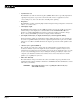
INTRODUCTION 1.3 Functional Options FIGURE 1.
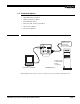
INSTALLATION 2 INSTALLATION The following instructions are provided to help you to set up your video camera system quickly and easily. It is suggested that you read through these instructions prior to unpacking and setting up your camera system. 2.1 Getting Started 2.1.1 Unpacking Instructions It is recommended that the original packing cartons for the cameras and lenses be saved in case there is a need to return or exchange an item.
INSTALLATION 2.2 Camera Setup 2.2.1 Connector Pin Configurations 2.2.1 (a) 12-Pin Connector 1 2 The TM-6703 has a 12-pin connector for power input. Description Pin# 8 10 3 Pin# 9 11 7 12 Description 1 GND 7 VD in (out OP7-2) 2 +12V DC 8 GND 3 GND 9 HD in (out OP7-2) 4 Video Out (clk out OP7-2) 10 N/C 5 GND 11 Integration 6 VINIT In 12 GND 4 6 5 2.2.
INSTALLATION If wiring the PD-12 power supply directly, please note the following • Twist the lead ends together and tin solder for strength and electrical continuity • Use shrink tubing or a similar insulator to prevent exposed leads from touching • The +12V lead is marked with a red stripe or white lettering; be sure not to reverse the leads • Properly insulate all connections to prevent shorting 2.2.
INSTALLATION Note: The “K” series power supplies are designed primarily for OEM users who will be mounting the power supply inside a protective enclosure. For use in exposed situations, the DC-12N and PD-12 are recommended. 2.2.
INSTALLATION 2.2.7 Auto Iris Lens Setup Auto-iris lenses with full video input (1 Vpp) can be used with the PULNiX TM-6703, although this camera model does not come equipped with auto-iris output. Note: Make sure that the power is removed from the camera before connecting or disconnecting the auto-iris lens. There is a small chance that damage could occur to the auto-iris lens by plugging or unplugging it while the camera is powered up.
OPERATION 3 OPERATION 3.1 Modes of Operation The TM-6703 is designed to accommodate a high resolution, on-line inspection reset mechanism with full frame shutter. It accepts external horizontal sync (HD, TTL Levels) to lock the camera and VINIT pulse for resetting the camera asynchronously. The shutter speed can be controlled by either an external double pulse, or by internal speed control by setting the 10-position shutter speed dial switch on the back panel. 3.1.
OPERATION 3.1.2 Driving /VINIT The TM-6703 VINIT input circuit equivalently has 10K ohm input resistance (Figure 4, “VINIT (Vertical Initialization) Trigger Specifications,” on page 10). To drive this circuit, at least 0.5mA of current is required to drive the camera. Note: FIGURE 4. The VINIT signal must be a defined, clean pulse for the asynchronous reset function to work properly. Some triggering systems (e.g., optical isolators, mechanical relays, noisy electrical devices, etc.
OPERATION Position Manual Shutter Mode Async Reset Mode 0 No Shutter No Shutter 1 1/125 1.0H 1/32,000 2 1/250 2.0H 1/16,000 3 1/500 4.0H 1/8,000 4 1/1,000 8.0H 1/4,000 5 1/2,000 16.0H 1/2,000 6 1/4,000 32.0H 1/1,000 7 1/8,000 64.0H 1/500 8 1/16,000 128.0H 1/250 9 1/32,000 Mode 0: Mode 1-4: Mode 5-8: Mode 9: Note: 78 9 01 2 3 The shutter control switch is located on the rear panel of the camera. The dial can be set from 0 to 9. The settings are detailed below.
OPERATION FIGURE 6. External Pulse Width Control (Async Mode) X External Pulse Width VINIT HD Internal VD 9H Transfer Gate Pulse 9H X Exposure Time Discharge pulse Composite Video 3.1.3 (b) Internal Fast Reset Mode (Async Mode) For Internal Reset Mode, set the 10-position dial switch from “1” to “4”. When this mode is selected, the camera resets with internal VD timing, which is latched to Hd, and video output is also synchronized with internal VD timing without further delay.
OPERATION 3.1.3 (c) Internal Slow Reset Mode (Async Mode) For Internal Slow Reset Mode, set the 10-position shutter speed dial switch from “5” to “8”. When the external VINIT pulse is applied, internal VD is latched to Hd and a second internal VD signal is generated to set up the shutter speed period. Video output timing starts right after the second internal VINIT. FIGURE 8. Internal Slow Reset External pulse VINIT min.
OPERATION 3.1.4 Progressive Scanning The TM-6703 uses a state-of-the-art CCD called a “Progressive scanning interline transfer CCD” which scans all lines sequentially from top to bottom at one frame rate (60 Hz). Like a non-interlace computer screen, it generates a stable crisp image without alternating lines and provides full vertical TV resolution of 484 lines. The interline transfer architecture is also important to generate simultaneous shuttering.
OPERATION FIGURE 9. Scan Output Center of Image Normal scan VD Partial scan VD (partial scan) Center 100 lines Fast dump 3.1.5 Option 7-2 In order to connect the TM-6703 camera to various frame grabbers, internal jumper settings allow the TM-6703 to accept external HD and VD sync at double speed (fH = 31.468 KHz), or to output HD, VD and pixel clock for variable scan frame grabbers. This option can be requested when ordering the TM6703. FIGURE 10.
OPERATION 3.1.7 Integration Integration times can vary depending on the specific application. Pin #11 of the 12-pin connector is integration control. It accepts standard TTL inputs. High is considered 5 volts, and Low is considered 0 volts. When a low is applied to pin #11, the integration process begins. Integration blocks the transfer gate of the image data out of the CCD array. Upon returning the signal back to high (which is required to end the process).
OPERATION 3.2 Board Layout and Adjustment 3.2.1 Top Board (Top Side) W5 W6 W7-W9 VR1 VR2 back plate VR3 VR4 VR5 VR7 AGC/MGC Left: AGC Right: MGC Gamma Down: On (0.45) Up: Off (1.0) CDS pulse delay adjustment AGC MGC Set at 2.0V Controlled from AGC MAX PED RG Vsub Set at 2.5V Set at 50 mV of video Factory adjustment only Factory adjustment only VSUB AGC MAX GAMMA PED RG 3.2.
TROUBLESHOOTING 4 TROUBLESHOOTING 4.1 Problems and Solutions Following are troubleshooting tips for common problems. Generally, problems can be easily solved by following these instructions. If the following remedies fail to offer a solution to your problems, please contact a PULNiX representative. 4.1.1 Symptom: No Video Remedies: Check that the following are properly connected and operational. • Power supplies • Power cables • Main power source • Shutter control • Async mode • Lens 4.1.
TROUBLESHOOTING 4.2 Information and Support Resources For further information and support: Phone: (408) 747-0300 (800) 445-5444 (800) 3-PULNIX (24-hour message access) Fax: (408) 747-0660 E-mail: imaging@jaipulnix.com Mail: PULNiX America Inc. Sales Department 1330 Orleans Drive Sunnyvale, CA 94089 ATTN: Video Applications Web Site: www.pulnix.
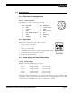
APPENDIX 5 APPENDIX 5.1 Specifications 5.1.1 Product Specifications TABLE 2. Product Specifications Table Imager Pixels Cell size Photosensitive Pixels 694 H x 496 V 9.0 H x 9.0 V µm 648 H x 484 V Output sensitivity 12µV/e- Micro lens Standard Scanning 525 lines at 60Hz (double speed mode) Sync Pixel clock TV resolution Min. illumination Video output Display mode video S/N ratio Internal/External auto switch HD/VD, 4.0 Vp-p impedance 4.7KΩ fHD = 31.468KHz / fVD = 60Hz 25.
APPENDIX 5.1.2 Physical Dimensions Physical Dimensions FIGURE 13. 140.8 mm 46.3 mm 128.1 mm VIDEO PULNiX 39.4 mm SHUTTER 9 0 1 2 8 3 7 6 5 4 ASY N O MAN P T GAIN POWER 7.0 mm 40 mm 2x 11.0 mm 1/4-20 UNC-2B 2x M3 x 8 30.
APPENDIX 5.1.3 Glass Specifications FIGURE 14. Camera Front End - Glass Specifications CCD Glass Cover CCD Glass CCD Glass (BK-7) 0.75mm thickness Refractive Index = 1.5 Glass Cover (BD-65) 1.0mm thickness Refractive Index = 1.51 5.1.4 C-Mount Specifications The Flange Back Length of the “CS-Mount” is 12.5mm versus 17.526 of the “C-Mount”. The shorter Flange Back Length of the “CS-Mount” allows room for the stripe filter incorporated in the color camera.
APPENDIX FIGURE 15. Combination With “CS-Mount” Camera CS-Mount Lens Focal Point 5mm Extension Ring C-Mount Lens 5 12.5 17.526 Flange Surface of C-Mount 5.1.5 Front End Detail FIGURE 16.
APPENDIX 5.2 Spectral Response FIGURE 17. Spectral Response 1.0 0.9 0.8 Relative Sensitivity 0.7 0.6 0.5 0.4 0.3 0.2 0.1 0 300 400 500 600 700 800 900 1000 1100 Wave Length (nm) 5.3 Block Diagram FIGURE 18. TM-6703 Block Diagram CCD TIMING GEN. Page 24 CDS & AMP SYNC GEN. SYNC ADDED PLL/XTAL VIDEO EXT.
APPENDIX 5.4 Timing Chart 5.4.1 Pixel Mapping (Horizontal) FIGURE 19. Pixel Mapping (Horizontal) HORIZONTAL RESET 45 TOTAL CLOCK PER 1H = 810 pixels 740 738 ACTIVE PIXEL 116 117 O.B. 10 11 DUMMY 1 764 738 739 740 741 DUMMY O.B. 60 CCD OUTPUT BLANK 202 PIXEL CLOCK OPTICAL BLACK ACTIVE PIXEL OPTICAL BLACK 694 691 690 682 35 683 DUMMY 34 11 1 10 CCD LINE CONTENT DUMMY 5.4.2 Vertical Frame Output Timing FIGURE 20.
, Industrial Products Division PULNiX America, Inc. 1330 Orleans Drive Sunnyvale, CA 94089 Tel: 408-747-0300 Tel: 800-445-5444 Fax: 408-747-0660 Email: imaging@jaipulnix.com www.pulnix.