
Specifications
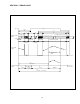


9.3 Mother Board
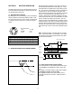
Standard YF
W1 Short Open
W2 Open Open
W3 Open Open
9.3 Imager Board
Connect imager board to test jig and check all
the functions.
Adjust and optimize Vsub voltage to specified
value on the imager back.
9.4 Factory Setting
AGC/MGC EXT. Switch
GAMMA 1.0/0.45 EXT. Switch
FLD/FRM EXT. Switch
SECTION 10
External Sync Version For TM-7EX/TM-6EX Only
10.1 External Sync Specification
Sync Internal/External auto-switching
HD in fHD = 15.734 KHz ± 5 % (EIA)
fHD = 15.625 KHz ± 5 % (CCIR)
VD in fVD = 59.94 Hz ± 5 % (EIA)
fVD = 50.0 Hz ± 5 % (CCIR)
Input impedance 200Ω
75Ω (optional)
See connector board R1,R2,R3 for termination
resistors.
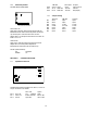
10.2 Connector Pin Configurations
TM-7EX/TM-6EX S-option
1GND GND
2+12V IN +12VIN
3GND GND
4VIDEO OUT VIDEO OUT
5N/C N/C
6Vinit in HD IN
7VD IN VD IN
8GND GND
9HD IN VINIT IN
10 N/C N/C
11 INT. CONT N/C
12 N/C N/C
10.3 Asynchronous Reset (Standard)
Asynchronous reset is available in all models. By pro-
viding reset input to Vinit pin, the TM-7 series camera
can reset the scanning within 1 µsec. The reset is done
for HD and VD together.
The reset pulse is TTL level and the negative going
edge is the reset timing.
This feature is especially useful for strobing applica-
tions which generate full frame resolution at random
reset. The captured image is always consistent with the
order of odd and even fields. Asynchronous reset also
eliminates "ghost image" which is caused by an over-
flow of charges when strong strobe lighting is applied
during the middle of imager scanning.
Asynchronous reset and asynchronous shutter:
Please refer to YF instruction.
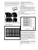
5
6
7
8
9
10
11
12
4
3
2
1
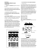
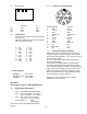
14
E9.0V F9.5V
G10.0V H10.5V
J11.0V K11.5V
L12.0V M12.5V
N13.0V P13.5V
Q14.0V R14.5V
S15.0V T15.5V
U16.0V V16.5V
W17.0V X 17.5V
Y18.0V Z18.5V
W3W2
W1
Mother Board