
Instruction manual

Page 10
Installation
TM-1402 Series Progressive Scan Shutter Cameras
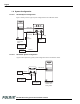
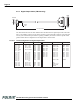
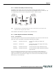
2.2.5 Digital Output Cable (TM-1402 only)
The TM-1402 camera uses the cable 30DG-02 from JAI PULNiX as a digital output cable. This cable
has a 31-pin AirBorn connector on the camera end and a 37-pin D-sub male connector on the other end.
Contact your JAI PULNiX representative regarding availability of interface cables for specific frame
grabber models. Pinout configuration for the digital cable is shown below.
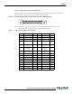
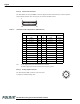
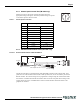
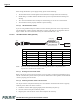
FIGURE 6. Pinout Configuration for Digital Output Cable
25.0mm
1.00 in
20
1
19
37
16
31
17
1
Female
78.74 in (2 meters)
Male
PIN 1 CLK+
PIN 2 LDV+
PIN 3 FDV+
PIN 4 GND
PIN 5 HD
PIN 6 INTEG
PIN 7 N/C
PIN 8 DØ+
PIN 9 D1+
PIN 10 D2+
PIN 11 D3+
PIN 12 D4+
PIN 13 D5+
PIN 14 D6+
PIN 15 D7+
PIN 16 NC
PIN 17 CLK-
PIN 18 CDV-
PIN 19 FDV-
PIN 20 VINIT
FROM 31 PIN CONN
PIN 1 CLK+
PIN 2 LDV+
PIN 3 FDV+
PIN 16 GND
PIN 37 INTEG
PIN 8 DØ+
PIN 9 D1+
PIN 10 D2+
PIN 11 D3+
PIN 12 D4+
PIN 13 D5+
PIN 14 D6+
PIN 15 D7+
NC
PIN 20 CLK-
PIN 21 LDV-
PIN 22 FDV-
PIN 17 VINIT
ORG 1RED
GRY 1RED
WHT 1RED
YLW 1RED
PNK 1RED
ORG 2RED
GRY 2RED
WHT 2RED
YLW 2RED
PNK 2RED
ORG 3RED
GRY 3RED
WHT 3RED
YEL 3RED
PNK 3RED
ORG 1BLU
GRY 1BLU
WHT 1BLU
YEL 1BLU
PIN 21 VD
PIN 22 N/C
PIN 23 GND
PIN 24 DØ-
PIN 25 D1-
PIN 26 D2-
PIN 27 D3-
PIN 28 D4-
PIN 29 D5-
PIN 30 D6-
PIN 31 D7-
PIN 18 NC
PIN 23 GND
PIN 27 DØ-
PIN 28 D1-
PIN 29 D2-
PIN 30 D3-
PIN 31 D4-
PIN 32 D5-
PIN 33 D6-
PIN 34 D7-
PIN 35 GND
N/C
PINS 4, 5, 6, 7
19, 24, 25,26,
AND 36
PNK 1BLU
ORG 2BLU
GRY 2BLU
WHT 2BLU
YLW 2BLU
PNK 2BLU
ORG 3BLU
GRY 3BLU
WHT 3BLU
YLW 3BLU
PNK 3BLU
SHIELD
TO 37 PIN CONN
WIRE COLOR
FROM 31 PIN CONN) TO 37 PIN CONN
WIRE COLOR