RU700A 1.0 User Manual v1.
RU700A 1.0 Puloli RU 700A 1.0 User Manual Version v1.1 Copyright © 2019 Puloli, Inc. All Rights Reserved. This publication may not be reproduced, in whole or in part, without specific and express prior written permission from Puloli, Inc. Puloli, Inc.
RU700A 1.0 Contents 1. About RU700A ........................................................................................................................................ 4 2. References .............................................................................................................................................. 4 3. Product Support and Contact Info ......................................................................................................... 4 4. Hardware Specification .......
RU700A 1.0 1. About RU700A The RU700A 1.0 is a research and development device intended for OEM integrators in specific industrial use as described in this document. It is not intended for general public consumer use-cases. It is strongly advised to consult the relevant references and to develop an understanding of the applicable underlying technology, tools, and methods before using this product. The RU700A 1.
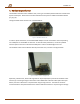
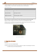
RU700A 1.0 4. Hardware Specification The RU700A 1.0 utilizes Puloli’s software stack, running on a hardware platform based on modules from Pycom and Sequans. Please refer to the documentation from Pycom for additional hardware details ([1], [2], [3]). The figure below shows the base unit of the RU700A 1.0: Figure 1. RU700A 1.0 base unit In order to power the device, the included USB AC adapter must be connected to the corresponding micro-USB port on the RU700A 1.0 base unit.
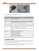
RU700A 1.0 Figure 3. Yagi antenna with attenuator and SMA-male to N-male coaxial patch cable The table below summarizes key attributes of the device. Table 1. RU700A 1.0 attributes Attribute Description Dimensions 65mm x 77mm x 28.5mm Weight 75g USB Power Supply The device shall only be used with the included AC adapter, which supplies 5V via a micro-USB connector when connected to a 100-240V 50/60Hz AC outlet. The power supply is ETL and FCC certified. RF connector SMA female, Taoglas CAB.
RU700A 1.0 The device will power up, initialize, perform a network search, and register itself on the network if coverage is available. The device status is indicated by an LED, as described below. Table 2.
RU700A 1.0 2. This device must accept any interference received, including interference that may cause undesired operation. CAUTION: Changes or modifications not expressly approved by the party responsible for compliance could void the user’s authority to operate the equipment. NOTE: This equipment has been tested and found to comply with the limits for a Class A digital device, pursuant to part 15 of the FCC Rules.