
Data Sheet
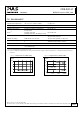
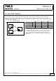
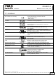
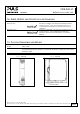
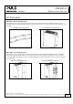
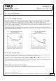
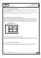
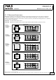
Table Of Contents
- 1. Intended Use
- 2. Installation Requirements
- 3. Input Voltage
- 4. Soft-start and Input Inrush Current Surge
- 5. Output
- 6. Hold-up Time
- 7. Efficiency and Power Losses
- 8. Functional Diagram
- 9. Front Side and User Elements
- 10. Terminals and Wiring
- 11. Reliability
- 12. EMC
- 13. Environment
- 14. Protection Features
- 15. Safety Features
- 16. Dielectric Strength
- 17. Approvals
- 18. RoHS, REACH and Other Fulfilled Standards
- 19. Physical Dimensions and Weight
- 20. Accessories
- 21. Application Notes
- 21.1. Peak Current Capability
- 21.2. Back-feeding Loads
- 21.3. Inductive and Capacitive Loads
- 21.4. External Input Protection
- 21.5. Requirements for the Supplying Source
- 21.6. Parallel Use to Increase Output Power
- 21.7. Parallel Use for Redundancy
- 21.8. Series Operation
- 21.9. Charging of Batteries
- 21.10. Use in a Tightly Sealed Enclosure
- 21.11. Mounting Orientations

CD5.241-L1
CD-Series
DC/DC Converter 24V, 3.8A
Mar. 2016 / Rev. 1.2 DS-CD5.241-L1-EN
All parameters are specified at 24V, 3.8A, 24Vdc input voltage, 25°C ambient and after a 5 minutes run-in time unless otherwise noted.
www.pulspower.com Phone +49 89 9278 0 Germany
21.11. MOUNTING ORIENTATIONS
Mounting orientations other than input terminals on the bottom and output on the top require a reduction in
continuous output power or a limitation in the max. allowed ambient temperature. The amount of reduction
influences the lifetime expectancy of the DC/DC converter. Therefore, two different derating curves for continuous
operation can be found below:
Curve A1 Recommended output current.
Curve A2 Max allowed output current (results in approximately half the lifetime expectancy of A1).
Fig. 21-4
Mounting
Orientation A
(Standard
orientation)
DC/DC
Converter
OUTPUT
Output Current
0
21/21
INPUT
20 30 40
50
70°
C
2
3
4A
60
A
1
Ambient Temperature
1
Fig. 21-5
Mounting
Orientation B
(Upside down)
DC/DC
Converter
OUTPUT
INPUT
Output Current
0
20 30 40
50
70°
C
2
3
4A
60
Ambient Temperature
1
A
2
A
1
Fig. 21-6
Mounting
Orientation C
(Table-top
mounting)
Output Current
0
20 30 40
50
70°
C
2
3
4A
60
Ambient Temperature
1
A
2
A
1
Fig. 21-7
Mounting
Orientation D
(Horizontal cw)
DC/DC
Converter
OUTPUT
INPUT
Output Current
0
20 30 40
50
70°
C
2
3
4A
60
Ambient Temperature
1
A
2
A
1
Fig. 21-8
Mounting
Orientation E
(Horizontal ccw)
DC/DC
Converter
OUTPUT
INPUT
Output Current
0
20 30 40
50
70°
C
2
3
4A
60
Ambient Temperature
1
A
2
A
1