
Datasheet


CP10.121, CP10.122
CP-Series
12V, 16A, 192W, SINGLE PHASE INPUT
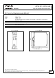
25.5. PARALLEL USE TO INCREASE OUTPUT POWER
Unit A
AC
DC
Unit B
AC
DC
-
+
-
+
Load
+
-
Power supplies can be paralleled to increase the output power. The output
voltage of all power supplies shall be adjusted to the same value (±100mV)
with the same load conditions on all units, or the units can be left with the
factory settings. There is no feature included which balances the load current
between the power supplies. Usually the power supply with the higher
adjusted output voltage draws current until it goes into current limitation. This
means no harm to this power supply as long as the ambient temperature stays
below 40°C.
If more than three units are connected in parallel, a fuse or circuit breaker with a rating of 25A or 32A is required on
each output. Alternatively, a diode or redundancy module can also be utilized.
Energize all units at the same time to avoid the overload Hiccup
PLUS
mode. It also might be necessary to cycle the input
power (turn-off for at least five seconds), if the output was in Hiccup
PLUS
mode due to overload or short circuits and the
required output current is higher than the current of one unit.
Keep an installation clearance of 15mm (left / right) between two power supplies and avoid installing the power
supplies on top of each other. Do not use power supplies in parallel in mounting orientations other than the standard
mounting orientation (terminals on bottom of the unit) or in any other condition where a derating of the output
current is required (e.g. altitude, …). Pay attention that leakage current, EMI, inrush current, harmonics will increase
when using multiple power supplies.
25.6. PARALLEL USE FOR REDUNDANCY
Power supplies can be paralleled for redundancy to gain higher system availability. Redundant systems require a
certain amount of extra power to support the load in case one power supply unit fails. The simplest way is to put two
decoupled power supplies in parallel. This is called a 1+1 redundancy. In case one power supply unit fails, the other
one is automatically able to support the load current without any interruption. Redundant systems for a higher power
demand are usually built in a N+1 method. E.g. five power supplies, each rated for 16A are paralleled to build a 64A
redundant system. For N+1 redundancy the same rules apply as for increasing the output power, see also chapter 25.5.
Please note: Always use a redundancy module to decouple power supplies from each other. This prevents that the
defective unit becomes a load for the other power supplies and the output voltage cannot be maintained any more.
Recommendations for building redundant power systems:
a) Use separate input fuses for each power supply.
b) Monitor the individual power supply units. Therefore, use the DC-OK relay contact of the CP10 power supply.
c) It is desirable to set the output voltages of all units to the same value (± 100mV) or leave it at the factory setting.
Fig. 25-5 1+1 redundant configuration with one YR40.242 redundancy module
25/28
Load
Failure
Monitor
optional
L
PE
N
I I
Power
Supply
Output
DC-
OK
+
-
+
-
o o
Input
L N
Power
Supply
Output
DC-
OK
+
-
+
-
o o
Input
L N
YR40.242
Redundancy
Module
Output
Input
1
Input
2
+
-
+
-
+
-
Aug. 2017 / Rev. 1.3 DS-CP10.121-EN
All parameters are typical values specified at 230Vac, 50Hz input voltage, 12V 16A output, 25°C ambient temperature and
after a 5 minutes run-in time unless otherwise noted.
www.pulspower.com Phone +49 89 9278 0 Germany