CP10.241, CP10.241-C1, CP10.241-S1, CP10.241-S2, CP10.242 24V, 10A, 240W, SINGLE PHASE INPUT CP-Series POWER SUPPLY AC 100-240V Wide-range Input Width only 39mm Efficiency up to 95.
CP10.241, CP10.241-C1, CP10.241-S1, CP10.241-S2, CP10.242 24V, 10A, 240W, SINGLE PHASE INPUT CP-Series INDEX Page 1. 2. 3. 4. 5. 6. 7. 8. 9. 10. 11. 12. 13. 14. 15. 16. 17. 18. 19. 20. 21. Intended Use .......................................................3 Installation Requirements...................................3 AC-Input...............................................................4 DC-Input...............................................................5 Input Inrush Current .....................
CP10.241, CP10.241-C1, CP10.241-S1, CP10.241-S2, CP10.242 CP-Series 24V, 10A, 240W, SINGLE PHASE INPUT 1. INTENDED USE This device is designed for installation in an enclosure and is intended for the general professional use such as in industrial control, office, communication, and instrumentation equipment. Do not use this power supply in equipment, where malfunction may cause severe personal injury or threaten human life. 2.
CP10.241, CP10.241-C1, CP10.241-S1, CP10.241-S2, CP10.242 24V, 10A, 240W, SINGLE PHASE INPUT CP-Series 3. AC-INPUT AC input AC input range External input protection Nom. AC 100-240V Suitable for TN-, TT- and IT mains networks Min. 85-264Vac Continuous operation Min. 264-300Vac For maximal 500ms Max. 300Vac Continuous according to IEC 62477-1 Nom. 50–60Hz ±6% Typ. 80Vac Steady-state value, see Fig. 3-1 Typ. 70Vac Steady-state value, see Fig. 3-1 Typ.
CP10.241, CP10.241-C1, CP10.241-S1, CP10.241-S2, CP10.242 24V, 10A, 240W, SINGLE PHASE INPUT CP-Series Fig. 3-3 Input current vs. output current at 24V output voltage Fig. 3-4 Power factor vs. output current at 24V output voltage Input Current, typ. Power Factor, typ. 3A a 2.5 b 1.0 2.0 1.5 (a) 0.95 a) 100Vac b) 120Vac c) 230Vac (b) 0.9 c 0.85 1.0 (a) 100Vac, (b) 120Vac, (c) 230Vac (c) 0.8 0.5 Output Current 0 1 2 3 4 5 6 7 8 Output Current 0.
CP10.241, CP10.241-C1, CP10.241-S1, CP10.241-S2, CP10.242 24V, 10A, 240W, SINGLE PHASE INPUT CP-Series 5. INPUT INRUSH CURRENT An active inrush limitation circuit (NTCs, which are bypassed by a relay contact) limits the input inrush current after turn-on of the input voltage. The charging current into EMI suppression capacitors is disregarded in the first microseconds after switch-on. Inrush current Max. Typ. Typ. Max. Inrush energy Fig.
CP10.241, CP10.241-C1, CP10.241-S1, CP10.241-S2, CP10.242 24V, 10A, 240W, SINGLE PHASE INPUT CP-Series 6. OUTPUT Output voltage Adjustment range Nom. Min. Max. Factory settings Line regulation Load regulation Ripple and noise voltage Output current Typ. Max. Max. Max. Nom. Nom. Nom. Nom. Nom. Nom. Typ. Overload behaviour Short-circuit current Output capacitance Min. Max. Max. Min. Typ. Typ. 24V 24-28V 30.
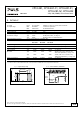
CP10.241, CP10.241-C1, CP10.241-S1, CP10.241-S2, CP10.242 24V, 10A, 240W, SINGLE PHASE INPUT CP-Series Fig. 6-2 Dynamic output current capability, typ. Fig. 6-1 Output voltage vs. output current, typ. Output Voltage Factory setting 16 28V Continuous current 24 20 Output Voltage (dynamic behavior, < 12ms) Adjustment Range 28V 24 Adjustment Range 20 16 12 12 HiccupPLUS mode 8 4 0 8 4 0 Output Current 2.5 0 5 7.5 10 12.5 15 17.5 20A Output Current 0 5 10 15 20 25 30 35 40 45 50A Fig.
CP10.241, CP10.241-C1, CP10.241-S1, CP10.241-S2, CP10.242 24V, 10A, 240W, SINGLE PHASE INPUT CP-Series 8. DC-OK RELAY CONTACT This feature monitors the output voltage on the output terminals of a running power supply. Contact closes Contact opens As soon as the output voltage reaches typ. 90% of the adjusted output voltage level. As soon as the output voltage dips more than 10% below the adjusted output voltage. Short dips will be extended to a signal length of 100ms.
CP10.241, CP10.241-C1, CP10.241-S1, CP10.241-S2, CP10.242 24V, 10A, 240W, SINGLE PHASE INPUT CP-Series 9. EFFICIENCY AND POWER LOSSES Efficiency Average efficiency*) Power losses *) Typ. Typ. Typ. AC 100V 92.9% 92.5% 92.5% AC 120V 93.6% 93.4% 93.0% AC 230V 95.2% 95.1% 94.3% Typ. Typ. Typ. Typ. 2.5W 9.8W 18.3W 23.4W 2.1W 8.9W 16.4W 21.7W 1.8W 7.1W 12.1W 14.8W At 24V, 10A At 24V, 12A (Power Boost) 25% at 2.5A, 25% at 5A, 25% at 7.5A.
CP10.241, CP10.241-C1, CP10.241-S1, CP10.241-S2, CP10.242 24V, 10A, 240W, SINGLE PHASE INPUT CP-Series 10. LIFETIME EXPECTANCY The Lifetime expectancy shown in the table indicates the minimum operating hours (service life) and is determined by the lifetime expectancy of the built-in electrolytic capacitors. Lifetime expectancy is specified in operational hours and is calculated according to the capacitor’s manufacturer specification.
CP10.241, CP10.241-C1, CP10.241-S1, CP10.241-S2, CP10.242 24V, 10A, 240W, SINGLE PHASE INPUT CP-Series 12. TERMINALS AND WIRING The terminals are IP20 Finger safe constructed and suitable for field- and factory wiring. CP10.241, CP10.241-C1, CP10.242 Type Solid wire Stranded wire American Wire Gauge Max. wire diameter (including ferrules) Recommended tightening torque Wire stripping length Screwdriver Input Screw termination Max. 6mm2 Max. 4mm2 AWG 20-10 2.8mm Max. 1Nm, 9lb-in 7mm / 0.28inch 3.
CP10.241, CP10.241-C1, CP10.241-S1, CP10.241-S2, CP10.242 24V, 10A, 240W, SINGLE PHASE INPUT CP-Series Daisy chaining: Daisy chaining is allowed for CP10.241, CP10.241-C1, CP10.241-S1 and CP10.242. Daisy chaining is not allowed for CP10.241-S2 Daisy chaining (jumping from one power supply output to the next) is allowed as long as the average output current through one terminal pin does not exceed 25A. If the current is higher, use a separate distribution terminal block as shown in Fig. 12-2. Fig.
CP10.241, CP10.241-C1, CP10.241-S1, CP10.241-S2, CP10.242 24V, 10A, 240W, SINGLE PHASE INPUT CP-Series 14. FRONT SIDE AND USER ELEMENTS Fig. 14-1 Front side CP10.241 A Fig. 14-2 Front side CP10.241-C1 Fig. 14-3 Front side CP10.241-S1 Fig. 14-4 Front side CP10.241-S2 Fig. 14-5 Front side CP10.242 Input Terminals CP10.241, CP10.241-C1, CP10.242: Screw terminals CP10.241-S1: Spring-clamp terminals CP10.
CP10.241, CP10.241-C1, CP10.241-S1, CP10.241-S2, CP10.242 CP-Series 24V, 10A, 240W, SINGLE PHASE INPUT 15. EMC The power supply is suitable for applications in industrial environment as well as in residential, commercial and light industry environments.
CP10.241, CP10.241-C1, CP10.241-S1, CP10.241-S2, CP10.242 24V, 10A, 240W, SINGLE PHASE INPUT CP-Series Switching Frequencies PFC converter Main converter Auxiliary converter 110kHz 84kHz to 140kHz 60kHz Fixed frequency Output load dependent Fixed frequency 16. ENVIRONMENT Operational temperature 1) Storage temperature Output de-rating Humidity Vibration sinusoidal 2) -25°C to +70°C (-13°F to 158°F) -40°C to +85°C (-40°F to 185°F) 3.2W/°C 6W/°C 5 to 95% r.h. Reduce output power according to Fig.
CP10.241, CP10.241-C1, CP10.241-S1, CP10.241-S2, CP10.242 24V, 10A, 240W, SINGLE PHASE INPUT CP-Series 17. PROTECTION FEATURES Output protection Output over-voltage protection Degree of protection Penetration protection Over-temperature protection Input transient protection Internal input fuse Electronically protected against overload, no-load and short-circuits. In case of a protection event, audible noise may occur. Typ. 30.5Vdc In case of an internal power supply defect, a redundant Max.
CP10.241, CP10.241-C1, CP10.241-S1, CP10.241-S2, CP10.242 24V, 10A, 240W, SINGLE PHASE INPUT CP-Series 19. DIELECTRIC STRENGTH The output voltage is floating and has no ohmic connection to the ground. Type and factory tests are conducted by the manufacturer. Field tests may be conducted in the field using the appropriate test equipment which applies the voltage with a slow ramp (2s up and 2s down). Connect all input-terminals together as well as all output poles before conducting the test.
CP10.241, CP10.241-C1, CP10.241-S1, CP10.241-S2, CP10.242 24V, 10A, 240W, SINGLE PHASE INPUT CP-Series 20. APPROVALS EC Declaration of Conformity The CE mark indicates conformance with the - EMC directive, - Low-voltage directive (LVD) and the - ATEX directive CB Scheme, Information Technology Equipment IEC 60950-1 2nd Edition UL 508 IND. CONT. EQ. UL 60950-1 2nd Edition ANSI / ISA 12.12.01-2015 Class I Div 2 (except CP10.241-S2) EN 60079-0, EN 60079-15 ATEX (except CP10.
CP10.241, CP10.241-C1, CP10.241-S1, CP10.241-S2, CP10.242 24V, 10A, 240W, SINGLE PHASE INPUT CP-Series 22. PHYSICAL DIMENSIONS AND WEIGHT Width Height Depth Weight DIN-Rail Housing material Installation clearances 39mm 1.54’’ 124mm 4.88’’ 117mm 4.61’’ The DIN-rail height must be added to the unit depth to calculate the total required installation depth. 600g / 1.3lb Use 35mm DIN-rails according to EN 60715 or EN 50022 with a height of 7.5 or 15mm.
CP10.241, CP10.241-C1, CP10.241-S1, CP10.241-S2, CP10.242 24V, 10A, 240W, SINGLE PHASE INPUT CP-Series 23. ACCESSORIES 23.1. ZM4.WALL – WALL/PANEL MOUNT BRACKET This bracket is used to mount the devices on a wall/panel without utilizing a DIN-Rail. It is suitable for the CP10.241, CP10.241-C1, CP10.241-S1 , CP10.241-S2 and CP10.242. The bracket can be mounted without detaching the DIN-rail brackets. Fig. 23-1 Isometric view (Picture shows the CP10.241) Fig.
CP10.241, CP10.241-C1, CP10.241-S1, CP10.241-S2, CP10.242 24V, 10A, 240W, SINGLE PHASE INPUT CP-Series 23.2. ZM12.SIDE - SIDE MOUNTING BRACKET This bracket is used to mount the power supply sideways with or without utilizing a DIN-Rail. The two aluminum brackets and the black plastic slider of the unit have to be detached, so that the steel brackets can be mounted. For sideway DIN-rail mounting, the removed aluminum brackets and the black plastic slider need to be mounted on the steel bracket. Fig.
CP10.241, CP10.241-C1, CP10.241-S1, CP10.241-S2, CP10.242 CP-Series 24V, 10A, 240W, SINGLE PHASE INPUT 23.3. YR20.242 - REDUNDANCY MODULE The redundancy module YR20.242 is equipped with two input channels, which are individually decoupled by utilizing MOSFET technology. Using MOSFETSs instead of diodes reduces the heat generation and the voltage drop between input and output. The YR20.
CP10.241, CP10.241-C1, CP10.241-S1, CP10.241-S2, CP10.242 24V, 10A, 240W, SINGLE PHASE INPUT CP-Series 24. APPLICATION NOTES 24.1. PEAK CURRENT CAPABILITY The unit can deliver peak currents (up to several milliseconds) which are higher than the specified short term currents. This helps to start current demanding loads. Solenoids, contactors and pneumatic modules often have a steady state coil and a pick-up coil.
CP10.241, CP10.241-C1, CP10.241-S1, CP10.241-S2, CP10.242 24V, 10A, 240W, SINGLE PHASE INPUT CP-Series 24.2. BACK-FEEDING LOADS Loads such as decelerating motors and inductors can feed voltage back to the power supply. This feature is also called return voltage immunity or resistance against Back- E.M.F. (Electro Magnetic Force). This power supply is resistant and does not show malfunctioning when a load feeds back voltage to the power supply. It does not matter whether the power supply is on or off.
CP10.241, CP10.241-C1, CP10.241-S1, CP10.241-S2, CP10.242 CP-Series 24V, 10A, 240W, SINGLE PHASE INPUT 24.5. SERIES OPERATION Unit A AC Power supplies of the same type can be connected in series for higher output voltages. It is possible to connect as many units in series as needed, providing the sum of the output voltage does not exceed 150Vdc. Voltages with a potential above 60Vdc are not SELV any more and can be dangerous. Such voltages must be installed with a protection against touching.
CP10.241, CP10.241-C1, CP10.241-S1, CP10.241-S2, CP10.242 24V, 10A, 240W, SINGLE PHASE INPUT CP-Series 24.7. PARALLEL USE FOR REDUNDANCY 1+1 Redundancy: Power supplies can be paralleled for redundancy to gain higher system availability. Redundant systems require a certain amount of extra power to support the load in case one power supply unit fails. The simplest way is to put two power supplies in parallel. This is called a 1+1 redundancy.
CP10.241, CP10.241-C1, CP10.241-S1, CP10.241-S2, CP10.242 24V, 10A, 240W, SINGLE PHASE INPUT CP-Series Wiring examples for 1+1 redundancy: Fig. 24-7 Wiring for N+1 redundancy with four power supplies and two redundancy modules YR20.242 Failure Monitor + + - - Output 24V,10A DCOK Power Supply - + - YR20.242 Redundancy Module + + - - + + Output 24V,10A o o DCOK - - + Output 24V,10A DCOK Power Supply - + - + + o o DCOK YR20.
CP10.241, CP10.241-C1, CP10.241-S1, CP10.241-S2, CP10.242 24V, 10A, 240W, SINGLE PHASE INPUT CP-Series 24.10. OPERATION ON TWO PHASES Power Supply L3 Center Tap 240V +10% max. L1 The power supply can also be used on two-phases of a three-phasesystem. Such a phase-to-phase connection is allowed as long as the supplying voltage is below 240V+10%. AC L N PE DC L2 24.11.
CP10.241, CP10.241-C1, CP10.241-S1, CP10.241-S2, CP10.242 24V, 10A, 240W, SINGLE PHASE INPUT CP-Series 24.12. MOUNTING ORIENTATIONS Mounting orientations other than all terminals on the bottom require a reduction in continuous output power or a limitation in the maximum allowed ambient temperature. The amount of reduction influences the lifetime expectancy of the power supply.