
Data Sheet
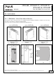
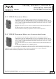

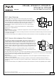
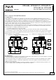
Table Of Contents
- 1. Intended Use
- 2. Installation Requirements
- 3. AC-Input
- 4. DC-Input
- 5. Input Inrush Current
- 6. Output
- 7. Hold-up Time
- 8. DC-OK Relay Contact
- 9. Efficiency and Power Losses
- 10. Lifetime Expectancy
- 11. MTBF
- 12. Terminals and Wiring
- 13. Functional Diagram
- 14. Front Side and User Elements
- 15. EMC
- 16. Environment
- 17. Protection Features
- 18. Safety Features
- 19. Dielectric Strength
- 20. Approvals
- 21. Other Fulfilled Standards
- 22. Physical Dimensions and Weight
- 23. Accessories
- 24. Application Notes
- 24.1. Peak Current Capability
- 24.2. Back-feeding Loads
- 24.3. External Input Protection
- 24.4. Output Circuit Breakers
- Series Operation
- Parallel Use to Increase Output Power
- 24.7. Parallel Use for Redundancy
- 24.8. Inductive and Capacitive Loads
- 24.9. Charging of Batteries
- Operation on Two Phases
- 24.11. Use in a Tightly Sealed Enclosure
- 24.12. Mounting Orientations

CP10.241, CP10.241-C1, CP10.241-S1,
CP10.241-S2, CP10.242
CP-Series
24V, 10A, 240W, SINGLE PHASE INPUT
Aug. 2017 / Rev. 1.4a DS-CP10.241-EN
All values are typical at 24V, 10A, 230Vac, 50Hz, 25°C ambient and after a 5 minutes run-in time unless otherwise noted.
www.pulspower.com Phone +49 89 9278 0 Germany
23.3. YR20.242 - REDUNDANCY MODULE
The redundancy module YR20.242 is equipped with two input channels, which are
individually decoupled by utilizing MOSFET technology. Using MOSFETSs instead of diodes
reduces the heat generation and the voltage drop between input and output. The YR20.242
does not require an additional auxiliary voltage and is self-powered even in case of a short
circuit across the output.
Due to the low power losses, the unit is very slender and only requires 32mm width on the
DIN-rail.
The YR20.242 can be used for N+1 and 1+1 redundancy systems.
Further information and wiring configurations can be found in chapter 24.7.
23.4. YR20.246 - REDUNDANCY MODULE WITH AUTOMATED LOAD SHARING
The redundancy module YR20.246 is equipped with two input channels, which are
individually decoupled by utilizing MOSFET technology. Using MOSFETSs instead of diodes
reduces the heat generation and the voltage drop between input and output. The YR20.246
does not require an additional auxiliary voltage and is self-powered even in case of a short
circuit across the output.
23/30
Due to the low power losses, the unit is very slender and only requires 32mm width on the
DIN-rail.
The YR20.246 is optimized for 1+1 redundancy systems.
Compared to the YR20.242, the YR20.246 is featured with an automated load sharing
between the connected power supplies. The YR20.246 monitors the function of the redundancy circuitry and provides
a signal in case of too high of output current, which could prevent redundancy, if one power supply fails.
Further information and wiring configurations can be found in chapter 24.7.