PRELIMINARY CP5.241, CP5.241-C1, CP5.241-S1, CP5.241-S2, CP5.242 24V, 5A, 120W, SINGLE PHASE INPUT CP-Series POWER SUPPLY AC 100-240V Wide-range Input Width only 32mm Efficiency up to 94.
PRELIMINARY CP5.241, CP5.241-C1, CP5.241-S1, CP5.241-S2, CP5.242 24V, 5A, 120W, SINGLE PHASE INPUT CP-Series INDEX Page 1. 2. 3. 4. 5. 6. 7. 8. 9. 10. 11. 12. 13. 14. 15. 16. 17. 18. 19. Intended Use .......................................................3 Installation Instructions ......................................3 AC-Input...............................................................5 DC-Input...............................................................6 Input Inrush Current ..................
PRELIMINARY CP5.241, CP5.241-C1, CP5.241-S1, CP5.241-S2, CP5.242 CP-Series 24V, 5A, 120W, SINGLE PHASE INPUT 1. INTENDED USE This device is designed for installation in an enclosure and is intended for commercial use, such as in industrial control, process control, monitoring and measurement equipment or the like. Do not use this device in equipment where malfunction may cause severe personal injury or threaten human life. 2.
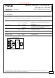
PRELIMINARY CP5.241, CP5.241-C1, CP5.241-S1, CP5.241-S2, CP5.242 CP-Series 24V, 5A, 120W, SINGLE PHASE INPUT Keep the following minimum installation clearances: 40mm on top, 20mm on the bottom, 5mm left and right side. Increase the 5mm to 15mm in case the adjacent device is a heat source. When the device is permanently loaded with less than 50%, the 5mm can be reduced to zero.
PRELIMINARY CP5.241, CP5.241-C1, CP5.241-S1, CP5.241-S2, CP5.242 24V, 5A, 120W, SINGLE PHASE INPUT CP-Series 3. AC-INPUT The device is suitable to be supplied from TN-, TT- and IT mains networks with AC voltage. For suitable DC supply voltages see chapter 4. Allowed voltage L or N to earth Input frequency Turn-on voltage Shut-down voltage External input protection Nom. AC 100-240V Min. 85-264Vac Continuous operation Min. 264-300Vac Occasionally for maximal 500ms Max.
PRELIMINARY CP5.241, CP5.241-C1, CP5.241-S1, CP5.241-S2, CP5.242 24V, 5A, 120W, SINGLE PHASE INPUT CP-Series 4. DC-INPUT The device is suitable to be supplied from a DC input voltage. Use a battery or a similar DC source. A supply from the intermediate DC-bus of a frequency converter is not recommended and can cause a malfunction or damage the unit. Connect +pole to L, –pole to N and the PE terminal to an earth wire or to the machine ground. DC input Nom. DC 110-150V Nom.
PRELIMINARY CP5.241, CP5.241-C1, CP5.241-S1, CP5.241-S2, CP5.242 24V, 5A, 120W, SINGLE PHASE INPUT CP-Series 5. INPUT INRUSH CURRENT An active inrush limitation circuit (NTCs, which are bypassed by a relay contact) limits the input inrush current after turn-on of the input voltage. The charging current into EMI suppression capacitors is disregarded in the first microseconds after switch-on. Inrush current Max. Typ. Typ. Max. Inrush energy Fig.
PRELIMINARY CP5.241, CP5.241-C1, CP5.241-S1, CP5.241-S2, CP5.242 24V, 5A, 120W, SINGLE PHASE INPUT CP-Series 6. OUTPUT The output provides a SELV/PELV rated voltage, which is galvanically isolated from the input voltage. The output is designed to supply any kind of loads, including capacitive and inductive loads. If extreme large capacitors, such as EDLCs (electric double layer capacitors or “UltraCaps”) with a capacitance > 0.
PRELIMINARY CP5.241, CP5.241-C1, CP5.241-S1, CP5.241-S2, CP5.242 24V, 5A, 120W, SINGLE PHASE INPUT CP-Series Fig. 6-1 Output voltage vs. output current, typ. Output Voltage Fig. 6-2 Dynamic output current capability, typ. Adjustment Range 28V Output Voltage (dynamic behavior, < 12ms) 28V 24 24 A 20 20 16 Adjustment Range 16 12 12 A: continuous current B: intermittent current 8 4 0 8 B 4 0 Output Current 1 0 2 3 4 5 6 7 8 9 10A Output Current 0 2.5 5 7.5 10 12.5 15 17.
PRELIMINARY CP5.241, CP5.241-C1, CP5.241-S1, CP5.241-S2, CP5.242 24V, 5A, 120W, SINGLE PHASE INPUT CP-Series 7. HOLD-UP TIME The hold-up time is the time during which a power supply’s output voltage remains within specification following the loss of input power. The hold-up time is output load dependent. At no load, the hold-up time can be up to several seconds. The green DC-ok lamp is also on during this time. Hold-up Time AC 100V 70ms 55ms 35ms 27ms Typ. Min. Typ. Min. Fig. 7-1 Hold-up time vs.
PRELIMINARY CP5.241, CP5.241-C1, CP5.241-S1, CP5.241-S2, CP5.242 24V, 5A, 120W, SINGLE PHASE INPUT CP-Series 9. EFFICIENCY AND POWER LOSSES Efficiency Average efficiency*) Power losses *) Typ. Typ. Typ. AC 100V 92.9% 92.7% 91.3% AC 120V 93.6% 93.5% 91.7% AC 230V 94.3% 94.5% 92.0% Typ. Typ. Typ. Typ. 1.3W 4.6W 9.2W 11.3W 1.3W 4.4W 8.2W 9.8W 1.4W 4.1W 7.3W 8.4W At 24V, 5A At 24V, 6A (Power Boost) 25% at 1.25A, 25% at 2.5A, 25% at 3.75A. 25% at 5A At 24V, 0A At 24V, 2.
PRELIMINARY CP5.241, CP5.241-C1, CP5.241-S1, CP5.241-S2, CP5.242 24V, 5A, 120W, SINGLE PHASE INPUT CP-Series 10. FUNCTIONAL DIAGRAM Fig. 10-1 Functional diagram L N Input Fuse Input Filter Input Rectifier Inrush Current Limiter PFC Converter Power Converter Output Filter Output Voltage Regulator Temperature Shutdown Output Power Manager Output OverVoltage Protection + + VOUT DC-ok LED Output Voltage Monitor DC-ok Relay DC-ok Contact 11. FRONT SIDE AND USER ELEMENTS Fig. 11-1 Front side CP5.
PRELIMINARY CP5.241, CP5.241-C1, CP5.241-S1, CP5.241-S2, CP5.242 24V, 5A, 120W, SINGLE PHASE INPUT CP-Series 12. CONNECTION TERMINALS The terminals are IP20 Finger safe constructed and suitable for field- and factory wiring. CP5.241, CP5.241-C1, CP5.242 Type Solid wire Stranded wire American Wire Gauge Max. wire diameter (including ferrules) Recommended tightening torque Wire stripping length Screwdriver Input Screw termination Max. 6mm2 Max. 4mm2 AWG 20-10 2.8mm Max. 1Nm, 9lb-in 7mm / 0.28inch 3.
PRELIMINARY CP5.241, CP5.241-C1, CP5.241-S1, CP5.241-S2, CP5.242 24V, 5A, 120W, SINGLE PHASE INPUT CP-Series 13. LIFETIME EXPECTANCY The Lifetime expectancy shown in the table indicates the minimum operating hours (service life) and is determined by the lifetime expectancy of the built-in electrolytic capacitors. Lifetime expectancy is specified in operational hours and is calculated according to the capacitor’s manufacturer specification.
PRELIMINARY CP5.241, CP5.241-C1, CP5.241-S1, CP5.241-S2, CP5.242 24V, 5A, 120W, SINGLE PHASE INPUT CP-Series 15. EMC The EMC behavior of the device is designed for applications in industrial environment as well as in residential, commercial and light industry environments. The device is investigated according to EN 61000-6-1, EN 61000-6-2, EN 61000-6-3 and EN 61000-6-4.
PRELIMINARY CP5.241, CP5.241-C1, CP5.241-S1, CP5.241-S2, CP5.242 24V, 5A, 120W, SINGLE PHASE INPUT CP-Series 16.
PRELIMINARY CP5.241, CP5.241-C1, CP5.241-S1, CP5.241-S2, CP5.242 24V, 5A, 120W, SINGLE PHASE INPUT CP-Series 17. SAFETY AND PROTECTION FEATURES Isolation resistance Min. 500MOhm Min. 500MOhm Min. 500MOhm Min. 500MOhm PE resistance Max. 0.1Ohm Output over-voltage protection Typ. Max. 30.5Vdc 32.0Vdc In case of an internal defect, a redundant circuit limits the maximum output voltage. The output shuts down and automatically attempts to restart.
PRELIMINARY CP5.241, CP5.241-C1, CP5.241-S1, CP5.241-S2, CP5.242 24V, 5A, 120W, SINGLE PHASE INPUT CP-Series 18. DIELECTRIC STRENGTH The output voltage is floating and has no ohmic connection to the ground. The output is insulated to the input by a double or reinforced insulation. Type and routine tests are conducted by the manufacturer. Field tests may be conducted in the field using the appropriate test equipment which applies the voltage with a slow ramp (2s up and 2s down).
PRELIMINARY CP5.241, CP5.241-C1, CP5.241-S1, CP5.241-S2, CP5.242 24V, 5A, 120W, SINGLE PHASE INPUT CP-Series 19. APPROVALS EC Declaration of Conformity IEC 60950-1 2nd Edition planned IEC 61010-2-201 2nd Edition planned ANSI/UL 61010-2-201 (former UL 508) planned The CE mark indicates conformance with the - RoHS directive - EMC directive and the - Low-voltage directive (LVD) CB Scheme for I.T.E. Information Technology Equipment Ind. Cont. Eq.
PRELIMINARY CP5.241, CP5.241-C1, CP5.241-S1, CP5.241-S2, CP5.242 24V, 5A, 120W, SINGLE PHASE INPUT CP-Series 21. PHYSICAL DIMENSIONS AND WEIGHT Width Height Depth Weight DIN-Rail Housing material Installation clearances Penetration protection CP5.241, CP5.241-C1, CP5.242 32mm 1.26’’ 124mm 4.88’’ 102mm 4.02’’ The DIN-rail height must be added to the unit depth to calculate the total required installation depth. 440g / 0.97lb Use 35mm DIN-rails according to EN 60715 or EN 50022 with a height of 7.
PRELIMINARY CP5.241, CP5.241-C1, CP5.241-S1, CP5.241-S2, CP5.242 24V, 5A, 120W, SINGLE PHASE INPUT CP-Series 22. ACCESSORIES 22.1. ZM10.WALL – WALL/PANEL MOUNT BRACKET This bracket is used to mount the devices on a wall/panel without utilizing a DIN-Rail. The bracket can be mounted without detaching the DIN-rail brackets. Fig. 22-1 Isometric view (Picture shows the CP5.241) Fig. 22-2 Isometric view(Picture shows the CP5.241) Fig. 22-3 Isometric view (Picture shows the CP5.241) Fig.
PRELIMINARY CP5.241, CP5.241-C1, CP5.241-S1, CP5.241-S2, CP5.242 CP-Series 24V, 5A, 120W, SINGLE PHASE INPUT 22.2. YR2.DIODE - REDUNDANCY MODULE The YR2.DIODE is a dual redundancy module, which can be used to build 1+1 or N+1 redundant systems. The device is equipped with two 10A nominal input channels, which are individually decoupled by utilizing diode technology. The output can be loaded with a nominal 20A continuous current.
PRELIMINARY CP5.241, CP5.241-C1, CP5.241-S1, CP5.241-S2, CP5.242 CP-Series 24V, 5A, 120W, SINGLE PHASE INPUT 22.5. UF20.241 BUFFER MODULE The UF20.241 buffer module is a supplementary device for DC 24V power supplies. It delivers power to bridge typical mains failures or extends the hold-up time after the AC power is turned off. When the power supply provides a sufficient voltage, the buffer module stores energy in the integrated electrolytic capacitors.
PRELIMINARY CP5.241, CP5.241-C1, CP5.241-S1, CP5.241-S2, CP5.242 24V, 5A, 120W, SINGLE PHASE INPUT CP-Series 23. APPLICATION NOTES 23.1. PEAK CURRENT CAPABILITY The unit can deliver peak currents (up to several milliseconds) which are higher than the specified short term currents. This helps to start current demanding loads. Solenoids, contactors and pneumatic modules often have a steady state coil and a pick-up coil.
PRELIMINARY CP5.241, CP5.241-C1, CP5.241-S1, CP5.241-S2, CP5.242 24V, 5A, 120W, SINGLE PHASE INPUT CP-Series 23.2. CHARGING OF BATTERIES The power supply can be used to charge lead-acid or maintenance free batteries. Two 12V SLA or VRLA batteries are needed in series connection. Instructions for charging batteries: a) Use only matched batteries when putting 12V types in series. b) Ensure that the ambient temperature of the power supply stays below 40°C.
PRELIMINARY CP5.241, CP5.241-C1, CP5.241-S1, CP5.241-S2, CP5.242 24V, 5A, 120W, SINGLE PHASE INPUT CP-Series 23.5. PARALLEL USE FOR REDUNDANCY Please note that there are variants with built-in redundancy are available in the CP5 series. Check CP5.241-Rx units. 1+1 Redundancy: Devices can be paralleled for redundancy to gain higher system availability. Redundant systems require a certain amount of extra power to support the load in case one device fails. The simplest way is to put two devices in parallel.
PRELIMINARY CP5.241, CP5.241-C1, CP5.241-S1, CP5.241-S2, CP5.242 24V, 5A, 120W, SINGLE PHASE INPUT CP-Series Fig. 23-6 N+1 Redundant configuration for 15A load current with multiple power supplies and redundancy modules Failure Monitor + + - - Output 24V,5A DCOK Power Supply - + - + + Redundancy Module - - + + Output 24V,5A DCOK YR20.242 Power Supply - - Output 24V,5A o o DCOK Power Supply + - + - + + o o DCOK YR20.
PRELIMINARY CP5.241, CP5.241-C1, CP5.241-S1, CP5.241-S2, CP5.242 24V, 5A, 120W, SINGLE PHASE INPUT CP-Series 23.6. OPERATION ON TWO PHASES Power Supply The power supply can also be used on two-phases of a three-phase-system. Such a phase-to-phase connection is allowed as long as the supplying voltage is below 240V+10%. 240V +10% max. Ensure that the wire, which is connected to the N-terminal, is appropriately fused. L1 L3 The maximum allowed voltage between a Phase and the PE must be below 300Vac.
PRELIMINARY CP5.241, CP5.241-C1, CP5.241-S1, CP5.241-S2, CP5.242 24V, 5A, 120W, SINGLE PHASE INPUT CP-Series 23.8. MOUNTING ORIENTATIONS Mounting orientations other than input terminals on the bottom and output on the top require a reduction in continuous output power or a limitation in the maximum allowed ambient temperature. The listed lifetime and MTBF values from this datasheet apply only for the standard mounting orientation.