
Datasheet

CP5.241, CP5.241-C1, CP5.241-S1,
CP5.241-S2, CP5.242
CP-Series
24V, 5A, 120W, SINGLE PHASE INPUT
Feb. 2018 / Rev. 0.3 DS-CP5.241-EN All parameters are typical values specified at 230Vac, 50Hz input voltage, 24V, 5A output load,
25°C ambient and after a 5 minutes run-in time unless otherwise noted.
www.pulspower.com Phone +49 89 9278 0 Germany
P R E L I M I N A R Y
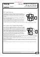
23.4. PARALLEL USE FOR REDUNDANCY
Please note that there are variants with built-in redundancy are available in the CP5 series. Check CP5.241-Rx units.
1+1 Redundancy:
Power supplies can be paralleled for redundancy to gain higher system availability. Redundant systems require a
certain amount of extra power to support the load in case one power supply unit fails. The simplest way is to put two
power supplies in parallel. This is called a 1+1 redundancy. In case one power supply unit fails, the other one is
automatically able to support the load current without any interruption. It is essential to use a redundancy module to
decouple power supplies from each other. This prevents that the defective unit becomes a load for the other power
supplies and the output voltage cannot be maintained any more.
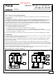
Recommendations for building redundant power systems:
- Use separate input fuses for each power supply.
- Use separate mains systems for each power supply whenever it is possible.
- Monitor the individual power supply units. Therefore, use the DC-OK signal of the power supply.
- It is desirable to set the output voltages of all units to the same value (± 100mV) or leave it at the factory setting.
- Set the power supply into “Parallel use” mode.
Pay attention that leakage current, EMI, inrush current, harmonics will increase when using multiple power supplies.
N+1 Redundancy:
Redundant systems for a higher power demand are usually built in a N+1 method. E.g. four power supplies, each rated
for 5A are paralleled to build a 15A redundant system.
Pay attention that leakage current, EMI, inrush current, harmonics will increase when using multiple power supplies.
Keep an installation clearance of 15mm (left / right) between two power supplies and avoid installing the power
supplies on top of each other.
Ensure that the ambient temperature stays below 40°C for AC 120-240V mains and below 35°C for AC 100V mains.
Energize all units at the same time to avoid the overload Hiccup
PLUS
mode. It also might be necessary to cycle the input
power (turn-off for at least five seconds), if the output was in Hiccup
PLUS
mode due to overload or short circuits and the
required output current is higher than the current of one unit.
Do not use power supplies in parallel in mounting orientations other than the standard mounting orientation or in
any other condition, where a reduction of the output current is required.
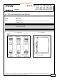
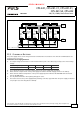
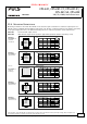
Wiring examples for 1+1 and N+1 redundancy:
Fig. 23-4 1+1 Redundant configuration for 5A load current with a
dual redundancy module
Fig. 23-5 1+1 Redundant configuration with active load share for
5A load current with a dual redundancy module
25/28
L
N
PE
5A
Load
Failure
Monitor
I
YR20.242
Redundancy
Module
Output
Input
1
Input
2
+ +
- -
+
-
optional
Power
Supply
24V,5A
DC-
OK
++
--
LNPE
Output
Input
o
o
Power
Supply
24V,5A
DC-
OK
++
--
LNPE
Output
Input
o
o
I
Note: A YR2.DIODE can also be used instead of a YR20.242
max.
5A
Load
Load
Share
Warning
I I
optional
YR20.246
Redundancy
Module
Output
1
Input
2
Input
++
--
+
-
Load Share
OK
o
o
Redudnadcy
OK
o
o
Failure
Monitor
L
N
PE
Power
Supply
24V,5A
DC-
OK
++
--
LNPE
Output
Input
o
o
Power
Supply
24V,5A
DC-
OK
++
--
LNPE
Output
Input
o
o