
User manual

CS10.241, CS10.241-S1
C–Series
24V, 10A, SINGLE PHASE INPUT
August 2006 / Rev. 1.1 DS-CS10.241-EN / All parameters are specified at 24V, 10A, 230Vac and 25°C ambient unless otherwise noted.
www.pulspower.com Phone +49 89 9278 0 Germany
18/20
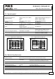
25.5. INDUCTIVE AND CAPACITIVE LOADS
The unit is designed to supply any kind of load, including unlimited capacitive and inductive loads.
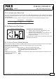
25.6. SERIES OPERATION
The power supply can be put in series to increase the output voltage.
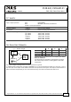
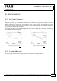
Fig. 25-5 Schematic for series operation
Instructions for use in series:
Earth
Unit A
AC
DC
Unit B
AC
DC
-
+
-
+
Load
+
-
a) It is possible to connect as many units in series as needed,
providing the sum of the output voltage does not exceed
150Vdc.
b) Voltages with a potential above 60Vdc are not SELV any
more and can be dangerous. Such voltages must be installed
with a protection against touching.
c) For serial operation use power supplies of the same type.
d) Earthing of the output is required when the sum of the
output voltage is above 60Vdc.
e) Keep an installation clearance of 15mm (left/right) between
two power supplies and avoid installing the power supplies
on top of each other.
Note:
Avoid return voltage (e.g. from a decelerating motor or
battery) which is applied to the output terminals.
25.7. PARALLEL USE TO INCREASE OUTPUT POWER
The power supply shall not be used in parallel to increase the output power.
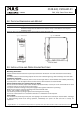
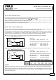
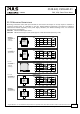
25.8. PARALLEL USE FOR 1+1 REDUNDANCY
Power supplies can be paralleled for 1+1 redundancy to gain a higher system availability. Redundant systems require
a certain amount of extra power to support the load in case one power supply unit fails. The simplest way is to put
two C-Series power supplies in parallel. In case one power supply unit fails, the other one is automatically able to
support the load current without any interruption. This simple way to build a redundant system has two major
disadvantages:
- The faulty power supply can not be recognized. The green LED will still be on since it is reverse-powered from
the other power supply.
- It does not cover failures such as an internal short circuit in the secondary side of the power supply. In such a -
virtually nearly impossible - case, the defective unit becomes a load for the other power supplies and the output
voltage can not be maintained any more.
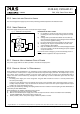
This can only be avoided by utilizing decoupling diodes which are included in the decoupling module YR2.DIODE or
redundancy module YRM2.DIODE.
Recommendations for building redundant power systems:
a) Use separate input fuses for each power supply.
b) Monitor the individual power supply units. A DC-ok lamp and a DC-ok contact is included in the redundancy
module YRM2.DIODE. This feature reports a faulty unit.
c) When possible, connect each power supply to different phases or circuits.