
Datasheet


CS10.241, CS10.241-S1
C–Series
24V, 10A, SINGLE PHASE INPUT
August 2006 / Rev. 1.1 DS-CS10.241-EN / All parameters are specified at 24V, 10A, 230Vac and 25°C ambient unless otherwise noted.
www.pulspower.com Phone +49 89 9278 0 Germany
16/20
25. APPLICATION NOTES
25.1. PEAK CURRENT CAPABILITY
Solenoids, contactors and pneumatic modules often have a steady state coil and a pick-up coil. The inrush current
demand of the pick-up coil is several times higher than the steady state current and usually exceeds the nominal
output current (including the PowerBoost) The same situation applies, when starting a capacitive load.
Branch circuits are often protected with circuit breakers or fuses. In case of a short or an overload in the branch
circuit, the fuse needs a certain amount of over-current to trip or to blow. The peak current capability ensures the
safe operation of subsequent circuit breakers.
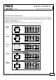
Assuming the input voltage is turned on before such an event, the built-in large sized output capacitors inside the
power supply can deliver extra current. Discharging this capacitor causes a voltage dip on the output. The following
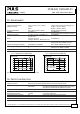
two examples show typical voltage dips:
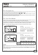
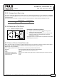
Fig. 25-1 Peak load 20A for 50ms, typ. Fig. 25-2 Peak load 50A for 5ms, typ.
10ms/DIV
Output
Voltage
Output
Current
24V
0A
20A
18.5V
1ms/DIV
Output
Voltage
Output
Current
24V
0A
50A
12V
Peak load 20A (resistive) for 50ms
Output voltage dips from 24V to 18.5V.
Peak load 50A (resistive) for 5ms
Output voltage dips from 24V to 12V.
25.2. CHARGING OF BATTERIES
The power supply shall not be used to charge batteries. Choose Q-Series for charging batteries.