
User Manual

1-Phase Power Supply Instruction Manual
Bedienungsanleitung für 1-Phasen Stromversorgung
EMC Electromagnetic Compatibility
These devices are suitable for applications in industrial environment as well as in residential,
commercial and light industry environment. Please note that for some units restrictions may apply
since the EN 61000-3-2 requirements are not fulfilled on all units. See also datasheet for details.
These devices comply with FCC Part 15 rules.
CE mark is in conformance with EMC directives 89/336/EC, 93/68/EC and 2004/108/EC and the
low-voltage directives (LVD) 73/23/EC, 93/68/EC, 2006/95/EC.
EMC Immunity: EN 61000-6-1, EN 61000-6-2
EMC Emission: For all units: EN 61000-3-3, EN 61000-6-4, FCC Part 15 Class B
EN 61000-6-3, EN 61000-3-2: For units which are marked with “Yes” in the
row EN 61000-3-2 of the technical data table.
EMV Elektromagnetische Verträglichkeit
Diese Geräte erfüllen die Anforderungen für Anwendungen sowohl in industrieller Umgebung als
auch für den Wohn-, Geschäfts- und Gewerbebereich. Einige dieser Gerätetypen erfüllen die
Anforderungen der EN 61000-3-2 nicht und es kann daher zu Einschränkungen bei
Anwendungen kommen. Siehe auch Details im Datenblatt. Die Geräte erfüllen auch die
Anforderungen der FCC Teil 15. Das CE Zeichen ist angebracht und erklärt die Erfüllung der EMV
Richtlinien 89/336/EG, 93/68/EG, 2004/108/EG und der Niederspannungsrichtlinien 73/23/EG,
93/68/EG, 2006/95/EG.
EMV Störfestigkeit: EN 61000-6-1, EN 61000-6-2
EMV Störaussendung: Für alle Geräte: EN 61000-3-3, EN 61000-6-4, FCC Part 15 Klasse B
EN 61000-3-2, EN 61000-6-3: Für Geräte, die in der Spalte EN 61000-
3-2 der Tabelle mit technischen Daten den Eintrag „Ja“ haben.
Installation
Use DIN-rails according to EN 60715 or EN 50022 with a height of 7.5 or 15mm. Mounting
orientation must be output terminals on top and input terminals on the bottom. For other
orientations see datasheet. Do not obstruct air flow as the unit is convection cooled. Ventilation
grid must be kept free of any obstructions. The following installation clearances must be kept
when power supplies are permanently fully loaded:
Left / right: 5mm (15mm in case the adjacent device is a heat source)
40mm on top, 20mm on the bottom of the unit.
Installation
Geeignet für DIN-Schienen entsprechend EN 60715 oder EN 50022 mit einer Höhe von 7,5 oder
15mm. Der Einbau hat so zu erfolgen, dass sich die Eingangsklemmen unten und die
Ausgangsklemmen oben befinden. Für andere Einbaulagen siehe Datenblatt. Luftzirkulation nicht
behindern! Das Gerät ist für Konvektionskühlung ausgelegt. Es ist für ungehinderte Luftzirkulation
zu sorgen. Folgende Einbauabstände sind bei dauerhafter Volllast einzuhalten:
Links / rechts: 5mm (15mm bei benachbarten Wärmequellen)
Oben: 40mm, unten 20mm vom Gerät.
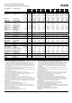
Input Fuses
All units have input fuses included (device protection, not externally accessible). The units are
tested and approved for branch circuits up to 20A. An external protection is only required if the
supplying branch has an ampacity greater than this. In some countries local regulations might
apply. Also check local codes and requirements. If an external fuse is necessary or utilized, the
following minimum ampacity value is necessary to avoid nuisance tripping of the circuit breaker.
CS3.241 CS10.243 CS5.241 CS5.243
CS10.xxx CS10.244 CS5.244
Internal Fuse T6.3A T6.3A T4A T4A
Min. Ampacity B- Characteristic B10A B16A B10A B16A
Min. Ampacity C- Characteristic C6A C10A C6A C10A
Sicherungen am Eingang
Die Geräte haben Sicherungen eingebaut (Gerätesicherung, nicht austauschbar durch Anwender)
und sind geprüft und zugelassen zum Anschluss an Stromkreisen bis max. 20A. Ein zusätzlicher
Schutz ist nur erforderlich, wenn der Speisestromkreis mit einem höheren Wert abgesichert ist
oder wenn nationale Richtlinien es fordern. Falls ein externes Schutzelement verwendet wird, soll
dieses den nachfolgenden Wert nicht unterschreiten, um ein fehlerhaftes Auslösen zu vermeiden.
CS3.241 CS10.243 CS5.241 CS5.243
CS10.xxx CS10.244 CS5.244
Interne Sicherung T6,3A T6,3A T4A T4A
Min. Sicherung B- Charakteristik B10A B16A B10A B16A
Min. Sicherung C- Charakteristik C6A C10A C6A C10A
Terminals and Wiring
The power supplies are equipped with screw terminals (except –S1 versions). Use appropriate
copper cables that are designed for an operating temperatures of 60°C (for ambient up to 45°C)
and 75°C (for ambient up to 60°C), minimum. Follow national installation codes and regulations!
Ensure that all strands of a stranded wire enter the terminal connection! Up to two stranded wires
with the same cross section are permitted in one connection point (except PE wire). Ferrules are
allowed, but not required.
Solid wire / Stranded wire / American wire gauge: 0.5-6mm
2
/ 0.5-4mm
2
/ 20-10 AWG
Wire stripping length: 7mm / 0.25inch
Screw driver: 3.5mm slotted or Philips No 2. (except S1 Versions)
Recommended tightening torque: 0.8Nm / 7lb.in (except S1 Versions)
Anschlussklemmen und Verdrahtung
Die Stromversorgungen sind mit Schraubklemmen ausgestattet (außer –S1 Versionen).
Verwenden Sie geeignete Kupferkabel, die mindestens für 60°C (bei einer Umgebungstemperatur
bis zu 45°C) und 75°C (bei einer Umgebungstemperatur bis zu 60°C) zugelassen sind. Beachten
Sie nationale Bestimmungen und Installationsvorschriften! Stellen Sie sicher, dass keine
einzelnen Drähte von Litzen abstehen. Bis zu zwei Leiter mit gleichem Querschnitt sind in einer
Klemme zulässig (außer für den Schutzleiter). Aderendhülsen sind erlaubt, aber nicht erforderlich.
Starrdraht / Litze / Amerikanischer Querschnitt: 0.5-6mm
2
/ 0.5-4mm
2
/ 20-10 AWG
Abisolierlänge: 7mm / 0.25inch
Schraubenzieher : 3,5mm Schlitzschraubendreher oder Philips No 2 (außer S1 Versionen)
Empfohlenes Anzugsdrehmoment: 0.8Nm / 7lb.in (außer S1 Versionen)
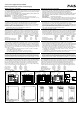
Output- and Overload Characteristic
The power supplies are overload, no-load, short-circuit proof. The units have power reserves of
20% included (except CS3). This extra current may even be used continuously at temperatures
up to +45°C (except CS10.242). At overload, the output current flows continuously. The units do
not switch-off or hiccup at overload. The characteristics can be found in the figures 1, 2, 3 and 4.
Ausgangs- und Überlastverhalten
Die Geräte sind leerlauf-, überlast- und kurzschlussfest. Die Geräte verfügen über 20% (außer
CS3) Reserveleistung, die bis zu einer Umgebungstemperatur von 45°C dauerhaft entnommen
werden kann (außer CS10.242). Bei Überlast fließt kontinuierlich Strom. Die Geräte schalten nicht
ab und haben auch keinen „Hiccup“ Modus. Das Verhalten ist in den Bildern 1, 2, 3 und 4 gezeigt.
Dielectric Strength (see Fig. 5)
The output voltage is floating and separated from the input according to SELV (IEC/EN 60950-1)
and PELV (EN 60204-1, EN 50178; IEC 62103, IEC 60364-4-41) requirements. Type and factory
tests are conducted by the manufacturer. Field tests may be conducted in the field using the
appropriate test equipment which applies the voltage with a slow ramp (2s up and 2s down).
Connect L and N together as well as all output poles before the test is conducted. When testing,
set the cut-off current settings to the value in the table below.
A B C
Type Test (60s) 2500Vac 3000Vac 500Vac
Factory Test (5s) 2500Vac 2500Vac 500Vac
Field Test (5s) 2000Vac 2000Vac 500Vac
Cut-off current setting > T.B.D. > T.B.D. > T.B.D.
Isolationsfestigkeit (siehe Bild 5)
Die Ausgangsspannung ist nicht geerdet und ist zum Eingang nach SELV (IEC/EN 60950-1) und
PELV (EN 60204-1, EN 50178, IEC 62103, IEC 60364-4-41) getrennt. Typ- und Stückprüfungen
werden beim Hersteller durchgeführt. Wiederholungsprüfungen dürfen mittels geeigneten
Prüfgenerators mit langsam (2s) ansteigenden und abfallenden Spannungsrampen in der
Anwendung erfolgen. Vor den Tests sind L und N wie auch alle Ausgangspole miteinander zu
verbinden. Die Strom- Abschaltschwelle muss größer als der in der Liste angegebene Wert sein.
A B C
Typprüfung (60s) 2500Vac 3000Vac 500Vac
Stückprüfung (5s) 2500Vac 2500Vac 500Vac
Wiederholungsprüfung (5s) 2000Vac 2000Vac 500Vac
Strom- Abschaltschwelle > T.B.D. > T.B.D. > T.B.D.
Fig. 1 / Bild 1
CS3.241
Fig. 2 / Bild 2
CS5.241, CS5.243, CS5.244
Fig. 3 / Bild 3
CS10.241, CS10.242, CS10.243, CS10.24
Fig. 4 / Bild 4
CS10.481
Fig. 5 / Bild 5
Insulation / Isolation
Output Voltage, typ.
0
04
4
8
12
28V
16
20
24
7
A
621 3 5
Adjustment
Range
Output Current
a) 100Vac
b) 120Vac
c) 230Vac
abc
Output Voltage, typ.
0
048
4
8
12
28V
16
20
24
12
A
1062
Adjustment
Range
Output Current
Output Voltage, typ.
0
04 81216
4
8
12
28V
16
20
24
20
A
10621418
A
djustment
Range
Output Current
+60°C
+25°C
-25°C
Output Voltage, typ.
0
02 468
10
20
60V
30
40
50
10
A
53179
Adjustment
Range
Output Current
+60°C
+25°C
-25°C
48V
52V
A
C
N
L
Input
Earth, PE
Output
-
+
B
CS3.xxx CS5.xxx, CS10.xxx CS3.241, CS5.241,
CS5.243, CS5.244
CS5.241-S1 CS10,241, C10,243,
CS10,244, CS10.481
CS10.241-S1
PU-360.011.00-10B