
User manual

CD5.121
CD–Series
DC/DC Converter; 12V, 8A
Jan. 08 / Rev. 1.1 DS-CD5.121-EN / All parameters are specified at 12V, 8A and 24Vdc input at 25°C ambient unless otherwise noted.
www.pulspower.com Phone +49 89 9278 0 Germany
12/21
16. PROTECTION FEATURES
Output protection Electronically protected against overload, no-load and short-circuits
Output over-voltage protection typ. 16.5Vdc
max. 16.8Vdc
In case of an internal DC/DC converter fault, a redundant
circuit limits the maximum output voltage. The output
shuts down and automatically attempts to restart.
Reverse input polarity protection included Unit does not start when input voltage is reversed
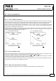
Output over-current protection electronically limited See Fig. 7-1
Degree of protection IP 20 EN/IEC 60529
Penetration protection > 3.5mm E.g. screws, small parts
Over-temperature protection yes Output shut-down with automatic restart
Input transient protection MOV Metal Oxide Varistor
Internal input fuse T10A H.B.C. Not user replaceable
An audible noise may be heard during a no load, overload or short circuit event.
17. SAFETY
Input / output separation SELV IEC/EN 60950-1
PELV EN 60204-1, EN 50178, IEC 60364-4-41
Double or reinforced insulation,
Max. allowed voltage between any input pin and ground: 60Vdc or 42.4Vac
Class of protection II PE (Protective Earth) connection not required
Isolation resistance > 5MOhm Input to output, 500Vdc
Chassis Ground resistance < 0.1Ohm Between housing and Chassis Ground terminal
Touch current (leakage current) The leakage current which is produced by the DC/DC converter itself depends on
the input voltage ripple and need to be investigated in the final application.
For a smooth DC input voltage, the produced leakage current is less than 100µA.
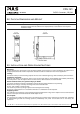
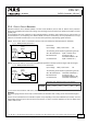
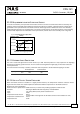
18. DIELECTRIC STRENGTH
Fig. 18-1 Dielectric strength
A B C
Type test 60s 1500Vac 1500Vac 500Vac
Factory test 5s 1500Vac 1500Vac 500Vac
Field test 5s 1000Vac 1000Vac 500Vac
A
C
B
+
Input
Chassis
ground
Output
-
+
-
Type tests and factory tests:
Conducted by the manufacturer. Do not repeat test in field!
Rules for field test:
Use appropriate test equipment which applies the voltage
with a slow ramp! Connect all input poles together as well
as all output poles.
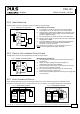
The output voltage is floating and has no ohmic connection to ground.
To fulfill the PELV requirements according to EN60204-1 § 6.4.1, it is recommend that either the + pole, the – pole or
any other part of the output circuit shall be connected to the protective earth system. This helps to avoid situations in
which a load starts unexpectedly or can not be switched off any more when an unnoticed earth faults occur.