
Datasheet
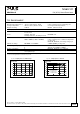
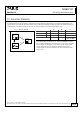
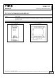
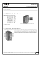
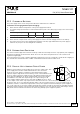
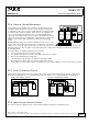
Table Of Contents
- 1. Intended Use
- 2. Installation Requirements
- 3. AC-Input
- 4. Input Inrush Current
- 5. Output
- 6. Hold-up Time
- 7. DC-Input
- 8. Efficiency and Power Losses
- 9. Functional Diagram
- 10. Front Side and User Elements
- 11. Terminals and Wiring
- 12. Lifetime Expectancy and MTBF
- 13. EMC
- 14. Environment
- 15. Protection Features
- 16. Safety Features
- 17. Dielectric Strength
- 18. Approvals
- 19. RoHS, REACH and Other Fulfilled Standards
- 20. Physical Dimensions and Weight
- 21. Accessory
- 22. Application Notes
- 22.1. Peak Current Capability
- 22.2. Back-feeding Loads
- 22.3. Charging of Batteries
- 22.4. External Input Protection
- Parallel Use to Increase Output Power
- Parallel Use for Redundancy
- 22.7. Daisy Chaining of Outputs
- 22.8. Inductive and Capacitive Loads
- Series Operation
- Operation on Two Phases
- 22.11. Use Without PE on the Input
- 22.12. Use in a Tightly Sealed Enclosure
- 22.13. Mounting Orientations
ML60.121
MiniLine-2
12V, 4.5A, SINGLE PHASE INPUT
22.6. PARALLEL USE FOR REDUNDANCY
20/23
Power supplies can be paralleled for redundancy to gain higher system
availability. Redundant systems require a certain amount of extra power
to support the load in case one power supply unit fails. The simplest way is
to put two power supplies in parallel. This is called a 1+1 redundancy. In
case one power supply unit fails, the other one is automatically able to
support the load current without any interruption. Redundant systems for
a higher power demand are usually built in a N+1 method. E.g. five power
supplies, each rated for 4.5A are paralleled to build a 18A redundant
system.
Please note: This simple way to build a redundant system does not cover
failures such as an internal short circuit in the secondary side of the power
supply. In such a case, the defect unit becomes a load for the other power supplies and the output voltage can not be
maintained any more. This can only be avoided by utilizing decoupling diodes which are included in the redundancy
module MLY10.241.
MLY10
IN 1
+
-
+
-
L
N
II
ML60.121
L N
Output
Input
+ +
- -
ML60.121
L N
Output
Input
+ +
- -
Output
Load
+
- -
+
-
IN 2
Voltage
Monitor
Recommendations for building redundant power systems:
a) Use separate input fuses for each power supply.
b) Use separate mains systems for each power supply whenever it is possible.
c) Monitor the individual power supply units.
d) 1+1 Redundancy is allowed up to an ambient temperature of 60°C.
N+1 Redundancy is allowed up to an ambient temperature of 45°C.
e) It is desirable to set the output voltages of all units to the same value (± 100mV) or leave it at the factory setting.
22.7. DAISY CHAINING OF OUTPUTS
Daisy chaining (jumping from one power supply output to the next) is allowed as long as the average output current
through one terminal pin does not exceed 25A. If the current is higher, use a separate distribution terminal block.
Fig. 22-3 Daisy chaining of outputs Fig. 22-4 Using distribution terminals
Power
Supply
+ +
- -
Input
Output
Load
+
-
max 25A!
Power
Supply
+ +
- -
Input
Output
Load
+
-
Distribution
Terminals
Power
Supply
+ +
- -
Input
Output Output
Power
Supply
+ +
- -
Input
22.8. INDUCTIVE AND CAPACITIVE LOADS
The unit is designed to supply any type of load, including unlimited capacitive and inductive loads.
Nov. 2015 / Rev. 1.4 DS--ML60.121-EN
All parameters are specified at 12V, 4.5A, 230Vac 50Hz input, 25°C ambient and after a 5 minutes run-in time unless otherwise noted.
www.pulspower.com Phone +49 89 9278 0 Germany