
User Manual

0
5
10
15
20
25
0 5 10 15 20 25 30
Jumper=Pos C
SilverLine
Deutsch Technische Daten
English Technical Data
Français Données Techniques
Español Datos Técnicos
Italiano Dati Tecnici
Português Dados Técnicos
DE
EN
FR
ES
IT
PT
SL20.110: Technische Daten
DE
Netzanschluß (AC
in
)
Eingangsspannung V
in
• Nennwert
Frequenz
• AC Dauerbetrieb
AC Kurzzeitig
(1 min.)
AC 100-120/220-240 V
Interne automatische
Bereichsumschaltung
47-63 Hz
85-132/184-264 V AC
85-140/170-280 V AC
Eingangsstrom I
in
• Nennwert I
n
Einschaltstrom
<10A / 5A (115/230V)
bei AC 264V, Kaltstart,
T
U
= +50°C (+25°C)
I
pk
< 37A (< 18A)
I
2
t< 8A
2
s (< 5A
2
s)
Powerfaktor (PFC):
Gerät erfüllt EN 61000-3-2 nicht
Externe Absicherung
• nationale Vorschriften beachten
• Leistungsschutzschalter mit B-Charakteristik
16A bzw. träger oder alternativ
Schmelzsicherung T16A HBC
Anschlußleitungen
c
• flexible Kabel
•starre Kabel
• Abisolieren am
Kabelende
0,5-4 mm
2
(AWG=20-10)
0,5-6 mm
2
(AWG=20-10)
7 mm (nicht länger!)
Größe, Gewicht
Breite w
Höhe h
Tiefe d
Gewicht
220 mm
124 mm
102 mm + DIN-Rail
1,8 kg
Umweltdaten
Umgebungstemperatur T
U
• Lagerung/Transport
• Vollast
•Derated
-25°C...+85°C
0°C...+60°C
+60°C...+70°C
Schutzart: IP20 (IEC60529),
Vor Feuchtigkeit (auch Betauung) schützen!
Normen, Zulassungen
Das Gerät erfüllt alle folgenden Normen:
EMV:
EN 61000-6-4 (Störaussendung)
(EN 55011, EN 55022, Klasse B);
EN 61000-6-2 und EN 61000-6-1 (Störfestigkeit)
VDE 0160/W2 (Transientenfest)
Sicherheit:
EN 60950, EN 60204-1, EN 50178,
IEC 60950, UL 60950, UL 508,
CAN/CSA-C22.2 No. 60950 (CUR)
CUL/CSA-C22.2 No. 14 (CUL)
CE-Kennzeichnung erfolgt nach EMV-Richtlinie
und Niederspannungsrichtlinie.
Anmerkungen/Hinweise:
a) sofern am Gerät nicht anders angegeben
b) Einzelbetrieb, 20 MHz Bandbr., 50Ω-Messung
c) siehe Beiblatt „Installation und Betrieb“ für
weitere Informationen
d) Hiccup-Modus = Abschalten und periodische
Wiederanlauf-Versuche
e) Einstellung erfolgt über Frontpotentiometer ().
Um Poti zu erreichen, Schutzkappe abziehen,
später wieder aufstecken.
Ausgang (DC
out
)
Nennspannung V
out
• Einstellgrenzen
minimal
• voreingestellt
a
• Regelgenauigkeit
• Restwelligkeit
b
24 V
24-28 V
e
24 V ± 0,5%
2 %
< 20 mV
SS
Zul. Belastung I
out
bei 24 V (28V), T
U
=0°C - 60°C
• dauerhaft
• kurzzeitig (<30 s)
• Derating (T
U
=60°-
70°C)
• Strombegrenzung
20 A (18 A)
25 A (22 A)
12 W/K
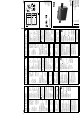
typ. 26 A (vgl. Fig.1)
Verhalten bei Überlast/Kurzschluß:
Umschaltbar per Jumper (s. Fig. 2a):
Dauerstrom (Pos. C, voreingestellt) oder Hiccup
d
(Pos. H, setzt ein bei Vout < ca. 14 V)
Achtung: Sekundärseite führt hohen
Strom!
Alle Leitungen, Anschlüsse und
sekundärseitigen Sicherungen entsprechend
auslegen!
Ausgangskennlinie umschaltbar
• gerade Kennlinie S für Einzelbetrieb
• weiche Kennlinie P für Parallelbetrieb
(25/29 V bei 0,4 A, 24/28 V bei Nennstrom)
Position des Jumpers für Umschaltung s. Fig. 2b).
Kennlinienverlauf: siehe Fig. 1
Parallelschaltung: ja, geneigte Kennlinie wählbar
über Steckbrücke
Anschlußleitungen
c
• flexible Kabel
•starre Kabel
• Abisolieren am
Kabelende
0,5-4 mm
2
(AWG=20-10)
0,5-6 mm
2
(AWG=20-10)
7 mm (nicht länger!)
Freiraum zur Kühlung
Gehäuseoberfläche an den Seiten darf nicht
wärmer als 90°C werden (Messung direkt am
Metall). Empfohlener Freiraum:
• links/rechts
•oben/unten
je 25 mm
je 70 mm
Sicherheit/Schutz
Sicherheitshinweise beachten!
Siehe Beiblatt
„Installation und Betrieb“
Sicherheit und Schutz
• Überspannungsschutz
(sekundärseit.)
• Überlastfest
• Dauerkurzschlußfest
• Leerlauffest
• Übertemperaturschutz
• Rückeinspeisefest
• Interne Eingangs-
sicherung
• Schutzklasse
• Sicherheits-
kleinspannung
, typ. 33 V
(Hiccup-Modus
d
)
(Hiccup-Modus
d
)
bis 30 V
–; ext. Sicherung:
siehe „Netzanschluß“
I (EN 60950)
SELV (EN 60950, VDE
0100 Part 410), PELV
(EN 50178)
SL20.110: Données Techniques
FR
Raccord de réseau (AC
in
)
Tension d'entrée V
in
• Valeur nominale
Fréquence
• AC, permanent
AC, temporaire (1 min.)
Courant d'entrée I
in
• Valeur nominale I
n
• courant de mise
en route
AC100-120/220-240V
Plage de fonctionnem. de
la tension d’entrée
47-63 Hz
85-132/184-264 V AC
85-140/170-280 V AC
< 10A /5A (115/230V)
à AC 264V, départ à
froid, T
amb
=
+50°C
(+25°C)
I
pk
< 37A (< 18A)
I
2
t< 8A
2
s (< 5A
2
s)
Facteur de puissance (PFC):
L’appareil ne répond pas à la norme EN 61000-3-2
Protection externe
• observez des règlements nationaux
• interrupteur de protection de conduite avec
caractéristique B 16A ou plus retardé, ou alors
coupe-circuit à fusible T16A HBC
Conduites de raccordement
c
• Câbles souples
• Câbles rigides
• Degainage en bout du
câble
0,5-4 mm
2
(AWG=20-10)
0,5-6 mm
2
(AWG=20-10)
7 mm (pas plus long!)
Dimensions, Poids
Largeur w
Hauteur h
Profondeur d
Poids
220 mm
124 mm
102 mm + profilé
1,8 kg
Données environnementales
Température ambiante T
amb
• Stockage/transport
• Pleine charge
•Derated
-25°C...+85°C
0°C...+60°C
+60°C...+70°C
Type de protection: IP20 (IEC60529),
protéger contre l’humidité (et la rosée)!
Normes, Autorisations
L’appareil répond aux normes suivantes:
CEM (Compatibilité électromagnétique):
EN 61000-6-4 (émission de perturbation)
(EN 55011, EN 55022, Classe B),
EN 61000-6-2 et EN 61000-6-1 (résistance aux
perturbation),
VDE 0160/W2 (résistance aux transitoires)
Sécurité:
EN 60950, EN 60204-1, EN 50178,
IEC 60950, UL 60950, UL 508,
CAN/CSA-C22.2 No. 60950 (CUR)
CUL/CSA-C22.2 No. 14 (CUL)
La caractérisation CE se fait selon la directive
CEM et la directive tension basse.
Remarques:
a) dans la mesure où aucun avis contraire n’est
indiqué sur l’appareil
b) en fonctionnement individuel, 20 MHz largeur
de bande, mesure 50 Ω
c) voir feuille annexe „Installation et fonctionne-
ment“ pour des informations supplémentaires
d) mode hiccup = arrêt et tentative périodique de
redémarrage
Sortie (DC
out
)
Tension nominale V
out
• Limites d’ajustem. min.
• Présélectionnée
a
• Précision de reglage
• Ondulation
rédiduelle
b
24 V
24-28 V
e
24 V ± 0,5%
2 %
< 20 mV
PP
Charge autorisée I
out
à 24 V (28V), T
amb
=0°C - 60°C
• permanent
• temporaire (<30 s)
• Derating (T
amb
=60°-
70°C)
• Limitation de courant
20 A (18 A)
25 A
(22 A)
12W/K
typ. 26 A (voir Fig.1)
Comportement en cas de surcharge/court-circuit:
commutable par jumper (voir Fig. 2a):
Courant permanent (pos. C, préselectionée) ou
mode hiccup
d
(pos. H, activé à Vout < env. 14 V)
Attention: Côté secondaire conduit du
courant fort!
Toutes les conduites, raccordement et
fusibles du côté secondaire sont à installer
en correspondance!
Caractéristique de sortie commutable:
• caract. droite S pour fonctionnement individuel
• caract. souple P pour fonctionnement parallèle
(25/29 V à 0,4 A, 24/28 V en pleine charge)
Position du jumper pour la commutation voir Fig. 2b.
Déroulement de la caractéristique: voir Fig. 1
Commutation en parallèle: oui, caractéristique
oblique sélectionnable par jarretière
Conduites de raccordement
• Câbles souples
• Câbles rigides
• Degainage
du câble
0,5-4 mm
2
(AWG=20-10)
0,5-6 mm
2
(AWG=20-10)
7 mm (pas plus long!)
Espace libre (refroidissement)
La surface du boîtier sur les côtés ne peut excéder
une température de 90°C (mesure directement sur
le métal). Espace libre recommandé:
•Gauche/Droite
• En-haut/En-bas
par 25 mm
par 70 mm
Securité, Protection
Respecter les
informations de sécurité!
Voir la feuille annexe
„Installation et fonctionnement“.
Securité/Protection:
protection/résistance
• contre la surtension
(côté secondaire)
• contre la surcharge
• aux court-circuits
perman.
• à la marche à vide
•contre la
surtemperature
• contre alimentation
en retour
• Fusible protect.
d'entrée interne
• Classe de protection
• Tension basse de
protection
, typ. 33 V
(mode hiccup
d
)
(mode hiccup
d
)
jusqu’a 30 V
–; Protect. ext..: voir
„Raccord de reseau“
I (EN 60950)
SELV (EN 60950, VDE
0100 Part. 410), PELV
(EN 50178)
Remarques (Suite):
e) Le réglage se fait par le potentiomètre ().
Pour atteindre poti, retirer le capot de protection
et le remettre ultérieurement.
SL20.110: Technical Data
EN
Connection to Mains (AC
in
)
Input Voltage V
in
•Nominal
Frequency
• AC continuously
AC short term
(1 min.)
Input Current I
in
•Nominal I
n
• Inrush current
AC 100-120/220-240 V
Internal automatic range
switching
47-63 Hz
85-132/184-264 V AC
85-140/170-280 V AC
<10A / 5A (115/230V)
at AC 264V, cold start,
T
amb
= +50°C (+25°C)
I
pk
< 37A (< 18A)
I
2
t< 8A
2
s (< 5A
2
s)
Power factor (PFC):
Unit does not fulfill EN 61000-3-2
External Fusing
• observe national regulations
• circuit breaker with B-characteristic 16A or
slower action, or alternatively T16A HBC fuse
Connector cables
c
• flexible cable
• solid wire
• stripping at cable end
0,5-4 mm
2
(AWG=20-10)
0,5-6 mm
2
(AWG=20-10)
7 mm (max)
Size, Weight
Width w
Hight h
Depth d
Weight
220 mm
124 mm
102 mm + DIN-Rail
1.8 kg
Environmental Data
Ambient temperature T
amb
• Storage/Shipment
• Full nominal load
• Derated
-25°C...+85°C
0°C...+60°C
+60°C...+70°C
Degree of protection: IP20 (IEC60529),
Protect from moisture (and condensation)!
Standards, Certifications
The unit fulfills all following standards:
EMC:
EN 61000-6-4 (Emissions)
(EN 55011, EN 55022, Class B),
EN 61000-6-2 and EN 61000-6-1 (Immunity)
VDE 0160/W2 (Transient protect.)
Safety:
EN 60950, EN 60204-1, EN 50178,
IEC 60950, UL 60950, UL 508,
CAN/CSA-C22.2 No. 60950 (CUR)
CUL/CSA-C22.2 No. 14 (CUL)
CE-Marking in compliance with EMC directive and
low-voltage directive.
Notes:
a) unless specified otherwise on the unit
b) Single operation, 20 MHz band width, 50Ω
measurement
c) See supplementary sheet „Installation and
Operation“ for further details
d) Hiccup mode = Switch-off and periodical restart
attempts
e) Setting is done by a front potentiometer (). In
order to reach potentiometer take off protective
cap and replace later
Output (DC
out
)
Rated Voltage V
out
• Adjustment limits,
min.
• Preset
a
• Accuracy of
regulation
• Ripple/Noise
b
24 V
24-28 V
e
24 V ± 0.5%
2 %
< 20 mV
PP
Permissible Load I
out
@ 24 V (28V),T
amb
=0-60°C
• permanent
• short term (< 30 s)
•Derating (T
amb
=60°-
70°C)
• Current limitation
20 A (18 A)
25 A (22 A)
12 W/K
typ. 26 A (see Fig.1)
Overload/Short circuit characteristic :
Selectable by jumper (s. Fig. 2a):
Continuous current (Pos. C, preset) or
Hiccup
e
(Pos. H, transition at Vout < ca. 14 V)
Warning: Secondary side carries
high current!
All lines, connectors and fuses on the
secondary side must be appropriately rated!
Output characteristic selectable:
• straight characteristic S for single operation
• load-dependent char. P for parallel operation
(25/29 V at 0.4 A, 24/28 V at rated current)
Jumper position for selection see Fig. 2b).
Characteristic curve: see Fig. 1
Parallel operation: yes, inclined characteristic
selectable by jumper
Connector cables
c
• flexible cable
• solid cable
• stripping at cable end
0,5-4 mm
2
(AWG=20-10)
0,5-6 mm
2
(AWG=20-10)
7 mm (max!)
Spacing for cooling
The maximum temperature at side walls must not
exceed 90°C (measuring directly on metal).
Recommended respective distances:
• left/right
• above/below
25 mm each
70 mm each
Safety/Protection
Read safety instructions!
See attached sheet
„Installation and Operation“
Safety and protection
• Overvoltage protection
(second. side)
• Resistant to overload
• Resistant to sustained
short-circuit
• Resistant to open-
circuit
• Overtemperature
protect.
• Reverse power
immunity
• Internal input fuse
• Protection class
• Extra low safety
potential
, typ. 33 V
(Hiccup mode
d
)
(Hiccup mode
d
)
up to 30 V
–; ext. fusing: see
„Connect. to mains“
I (EN 60950)
SELV (EN 60950, VDE
0100 Part 410), PELV
(EN 50178)
SL20.110
(Rev. C)
PU-304.013.00-10D
US Patent No. DES. 424, 529
© 2004 by
PULS GmbH
Arabellastraße 15
D-81925 München
Germany
Tel.: +49 89 9278-0
Fax: +49 89 9278-299
sales@puls-power.com
www.puls-power.com
Rev.: 09/2004
CB
scheme
Fig. 1: V
out
vs. I
out
(typ.)
Fig. 2
V
out
Jumper=Pos H: Vout < ca. 14V: Hiccup
I
out
a) b)