
Owner's manual


6
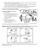
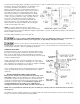
DOWN-THE-WELL INSTALLATION:
Often it is desirable to provide chemical feed
near the intake of the well pump for
additional retention time and mixing of the
chemicals. An additional length of discharge
tubing will be required for this installation.
Secure the end of the discharge tubing to the
pump cylinder, drop pipe, or foot valve and
lower it into the well. An anti-siphon valve
must be installed on systems such as this
where the discharge is lower than the feeder
and the chemical storage tank.
Failure to install anti-siphon valve may
allow siphoning to occur.
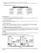
ANTI-SIPHON VALVE: (optional)
Under any installation condition where the
possibility of siphoning or suction may occur
on the discharge side of the pump, install an
anti-siphon valve on the discharge side of the
feeder. The anti-siphon valve is not part of
the standard package. This item can be furnished by your dealer at extra cost.
PRESSURE RELIEF VALVE: (optional)
Series 100/150 chemical pumps are rated to pump against a line pressure up to
100 PSI (7 BAR). If the line pressure on an installation could fluctuate above 100
PSI (7 BAR), install a pressure relief valve on the discharge side of the pump
head. Once the pressure reaches a certain level, the pre-set relief valve will
return the solution being pumped back to the solution tank. This will prevent
motor burnout or diaphragm rupture. The relief valve is not part of the standard
package. This item can be furnished by your dealer at extra cost. Read relief
valve instructions carefully before installing.
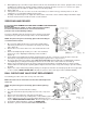
BLEED VALVE INSTALLATION: (optional)
NOTE: After disconnecting power to the pump and taking necessary safety
precautions regarding the chemical and system.
1. Remove the coupling nut and tubing from the discharge port of the pump.
2. Remove the valve housing from the discharge side of the pump head and
replace it with the .38inch valve housing from the kit (this step is not required
if the pump is already fitted for .38inch tubing.
3. Install the TFE gasket over the discharge fitting.
4. Install the bleed valve assembly over the discharge fitting and gasket.
5. Install the bypass tubing from the kit into the bypass port of the bleed valve
and hand-tighten the coupling nut. Bypass tubing should be connected to
return bypassed liquid back to the solution tank.
6. Install the discharge tubing into the discharge port of the bleed valve and hand tightens the coupling nut.