
Owner's manual


9
4. When light finger pressure will no longer allow movement of the knob between cam contacts, grasp the knob securely
and tighten the locking lever (turning clockwise) making sure that the knob does not move. To check for zero point,
turn on pump. There should be no liquid coming out of discharge fitting.
5. Replace dial stop.
6. If the pointer is not at "0", loosen the set-screw on the knob (use a .078 in Hex key), and turn pointer to "0", then
retighten the set-screw while holding the knob in place.
7. A setting of "0" will now give zero output. One full revolution of the knob counter clockwise will give maximum output.
The knob should never be turned more than one full revolution.
SERVICING AND REPAIRS
REPLACEMENT OF PUMP HEAD ASSEMBLY OR DIAPHRAGM:
Before performing any repairs on Series 100/150 chemical feeders,
be sure to disconnect all electrical connections and relieve
pressure from suction/discharge tubing.
The Series 100/150 feeder was designed so that servicing can be quick
and simple. Proper part replacement procedures are described below.
NOTE: Use protective gloves and safety glasses when working on
or around chemical feeder.
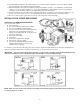
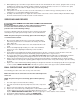
1. Disconnect the tubing. Remove the suction valve and discharge
valve being careful not to lose the ball checks and any other small
parts. (Figure N)
2. Remove the four screws from the face of the head and remove the
head.
3. Remove the diaphragm by inserting one or two of the head bolts
into the holes of the diaphragm and turning counter-clockwise.
(Figure O)
4. A new pump head or diaphragm should be installed if either is broken or cracked (see parts list at the end of this
manual). The new pump head can be installed by going through the above steps in reverse.
5. Be sure the drive bracket assembly is in the fully retracted position when installing the new diaphragm. Install the
new diaphragm by screwing it in hand tight, then, back off one-fourth turn or until screw holes are lined up.
6. Replace the head and the head screws, being certain the discharge fitting is up. NOTE: Arrow on outside of pump
head should be in vertical position pointing upward. Tighten the head screws evenly and carefully to prevent cracking
the head.
7. Replace the suction and discharge fittings making sure all gaskets and valves are fitted properly. Do not use pipe tape
or other sealants. HAND TIGHTEN ONLY. Restart the system as in the start up procedures (INSTALLATION).
BALL CHECKS AND VALVE SEAT REPLACEMENT:
The following procedure is the same for any of the four valves.
Make sure all electrical connections are disconnected and pressure
valves off.
NOTE: Use protective gloves and safety glasses while replacing
parts.
1. Unscrew compression nut and remove tubing.
2. Unscrew check valve body from pump head, foot valve, or injection
fitting.
3. Remove all seats, ball checks, and gaskets and replace.
4. Replace the check valve body so fitting makes contact with the gasket
and the pump head, foot valve or injection fitting, whichever the case
may be. HAND-TIGHTEN FITTINGS ONLY. Do not use pipe tape or other sealants on these threads.
5. Re-install the tubing and tighten coupling nut HAND TIGHT.
6. Restart the system as in the INSTALLATION PROCEDURES.