Installation, Operation & Maintenance Instruction Models: GLM M1 – 6 PULSA GLM® Bulletin #: IOM-GLM-1303-A MECHANICAL DIAPHRAGM METERING PUMP
Pulsafeeder Factory Service Policy Pulsafeeder’s Factory Service Policy is maintained on its website. Please source this document at this URL: http://www.pulsa.com/downloads/pdf/Pulsafeeder%20EPO%20Limited%20Warranty%20Statement.pdf Safety Considerations: 1. Read and understand all related instructions and documentation before attempting to install or maintain this equipment. 2. Observe all special instructions, notes, and cautions. 3.
Table of Contents 1. EQUIPMENT INSPECTION ....................................................................................................................... 1 2. INSTALLATION ...................................................................................................................................... 1 2.1 Location ................................................................................................................................... 1 2.2 Motor ...................................
1. Equipment Inspection Check all equipment for completeness against the order and for any evidence of shipping damage. Shortages or damage must be reported immediately to the carrier and your authorized representative or distributor of PULSA GLM® pumps. Included Items: • PULSA GLM® Metering Pump with Motor Adaptor Optional Items: • Motor (pre-installed at the factory) • Foot Valve Kit (provided on PULSA GLM® models M1 and M2 only). 2. Installation Figure 1: Foot Valve Kit 2.
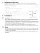
2.3 Piping System Attention to piping detail will assure an easy startup and long life of your GLM®. Please follow these guidelines: Suction Piping Isolation Valve and Unions: Isolation valves allow the system to be isolated from the process fluid to facilitate safe servicing. They also aid in the operation of Calibration columns. Valves should include good visible indications of open/closed condition. Unions assist with installation and maintenance. Valves that integrate union fittings are ideal.
Piping System Recommendations 1. When making the threaded joint to the valve cap assembly, use a sealing compound chemically compatible with the process material (for example Loctite® 8551 [Loctite is a registered Trade Mark of Henkel Corporation] for water service). Do not use sealing tape. The valve cap should be tightened by hand and then tightened 1 additional turn (i.e., 360 degrees) with the aid of an adjustable wrench. 2.
2.5 Discharge Pressure Requirements All PULSA GLM® metering pumps are designed for continuous service at the rated discharge pressure. If the system suction pressure exceeds the discharge pressure (a condition sometimes described as “pumping downhill”), flow will be generated in addition to that generated by the pump. This results in a reduction in accuracy and loss of control over the metering process.
3. Equipment Startup 3.1 Fastener Inspection All pump fasteners should be checked prior to pump operation, and occasionally during use. This would include reagent head mounting bolts, motor mounting bolts, and the hardware that secures the pump to its foundation. Figure 5: Reagent Head Bolt tightening The motor and reagent head mounting bolts should be torqued to 4.5 N-M (40 IN-LBF).
3.3 Priming the Reagent Head 1. When handling process liquids, follow all applicable personal and facility safety guidelines. 2. Ensure that the pump is ready for operation and that all process connections are secure. 3. Open the suction and discharge line shutoff valves. 4. If the piping system design and the storage tank are such that the product flows due to gravity through the pump, reduce the discharge pressure and the system will self prime when the pump is started.
3.4 Calibration Figure 8: Sample Flow Calibration Curve All metering pumps must be calibrated to accurately correlate stroke length settings to measured flow rates. A typical calibration chart is shown above. Although output is linear with respect to the stroke length setting, an increase in discharge pressure decreases output uniformly, describing a series of parallel lines, one for each pressure (only two are shown).
4.1 Lubrication PULSA GLM® pumps have an oil bath reservoir that is pre-filled with 250mL of PULSAlube 9M at the factory. For optimum pump performance under normal conditions, the PULSAlube 9M should be replaced every 3,000 hours. For severe service in non-temperature controlled and/or dirty environments the PULSAlube 9M should be replaced every 1,500 hours. 1. Disconnect the power source to the drive motor, and relieve all pressure from the piping system. 2.
4.2 Wet End Removal, Inspection, & Reinstallation IF THE DIAPHRAGM HAS FAILED, PROCESS FLUID MAY HAVE CONTAMINATED OTHER PARTS OF THE PUMP INCLUDING THE DRIVE COMPONENTS (ALTHOUGH NORMALLY, ANY PROCESS FLUID BEHIND A FAILED DIAPHRAGM WOULD PASS THROUGH THE BOTTOM DRAIN HOLE). HANDLE WITH APPROPRIATE CARE.
4.2.1 Diaphragm Removal & Reinstallation 1. Adjust the stroke setting to 50% and disconnect the power source to the drive motor. 2. Relieve all pressure from the piping system. 3. Close the inlet and outlet shutoff valves. 4. Place a pan underneath the pump head adaptor to catch any liquid leakage. 5. Disconnect piping to the reagent head and drain any process liquid, following all recommended material safety precautions. 6. Remove all but one top reagent head bolt.
4.3 4.3.1 Check Valves General Description The valve incorporates a ball, guide, and seat. Flow in the unchecked direction lifts the ball off the seat, allowing liquid to pass through the guide. Reverse flow forces the ball down, sealing it against the bevel edge of the seat and o-ring. The guide permits the ball to rotate but restricts vertical and lateral movement in order to minimize “slip” or reverse flow. Ball rotation prolongs life by distributing wear over the entire surface of the ball.
4.3.3 Check Valve Removal & Reinstallation, Tie-bar type 1. Disconnect and Lockout the power supply to the drive motor. 2. Relieve all pressure from the piping system. 3. Take all precautions necessary to prevent contamination to the environment and personnel exposure to hazardous materials. 4. Close the inlet and outlet shutoff valves. 5. Loosen the suction valve tie-bar bolts (4) and spring the suction piping slightly away from the head, allowing liquid to drain.
4.4 Motor Removal & Reinstallation Removal 1. Disconnect and Lockout the power supply to the drive motor. 2. Disconnect the motor wiring from the motor. 3. Remove the four bolts retaining the motor to the motor adaptor. 4. The motor shaft is keyed to a plastic coupling that slides into a splined bore in the pump input shaft. Lift the motor straight up to slide the motor shaft coupling out of the pump input shaft. Installation 1. Install the plastic coupling over the motor key onto the motor shaft.
4.5 Pump Head Removal The PULSA GLM® includes a Pump Head that clamps the diaphragm to the Reagent Head. In the event of diaphragm failure process fluid can come into contact with this part (it includes a drain hole to prevent fluid accumulation). Over time, it is possible for this part to suffer some level of deterioration and need replacement. 1. Disconnect and Lockout the power supply to the drive motor. 2. Relieve all pressure from the piping system. 3.
5. Replacement Parts 5.1 KOPkit Program PULSA GLM® KOPkits contain all replacement parts normally used in a preventative maintenance program. (PULSAlube is also available separately for preventative maintenance programs. Refer to Section 3 – Equipment Startup). There is a specific KOPkit for every PULSA GLM® pump model. Each KOPkit is vacuum-packed for extended storage. All PULSA GLM® pumps have the KOPkit number identified on the pump nameplate and Pulsafeeder order documents.
5.
6. Troubleshooting Difficulty Pump motor does not start Probable Cause Faulty power source. Blown fuse, circuit breaker. Broken wire. Wired improperly. Process piping blockage. No fluid delivery Motor not running. Supply tank empty. Line clogged. Closed in-line valve(s). Ball check valves held open with solids. Vapor lock, cavitation. Prime lost. Strainer clogged. Low fluid delivery Stroke adjustment set at zero. Motor speed too low. Check valves worn or dirty. Calibration system error.
Difficulty Piping noisy. Probable Cause Pipe size too small. Motor overheats. Pipe runs too long. Pulsation dampener inoperative or flooded. No surge chamber or dampener used. Pump overloaded. High or low voltage. Loose wire. Incorrect motor wiring. 18 Remedy Increase size of piping - install pulsation dampener. Install pulsation dampener in line. Refill with air or inert gas. Inspect and replace diaphragm and recharge. Install pulsation dampeners. Check operating conditions against pump design.
7. Piping Accessories Pressure Relief Valves Pressure relief valves are designed to protect chemical feed systems from damage that may be caused by defective equipment or a blockage in the discharge line. These valves function to limit the pressure downstream of the pump. Field adjust the pressure relief valve to operate when the discharge pressure exceeds operating pressure by 10-15%. Pressure relief valve should always be adjusted to a setting below the maximum rated pressure of the pump.
8.
Dimension Model A 71 B C D E F 95.5 / 3.8 300.0 / 11.8 94.5 / 3.7 85.5 / 3.4 37.0 / 1.5 95.5 / 3.8 315.0 / 12.4 94.5 / 3.7 95.8 / 3.7 37.0 / 1.5 95.5 / 3.8 325 / 12.8 94.5 / 3.7 99.3 / 3.9 37.0 / 1.5 160.0 / 6.3 DM1 & DM2 56C 196.0 / 7.7 71 160.0 / 6.3 DM3 & DM4 56C 196.0 / 7.7 71 160.0 / 6.3 DM5 & DM6 56C 196.0 / 7.7 Dimension Model G H 340.0 / 13.4 170.0 / 6.7 56C 420.0 / 16.5 175.0 / 6.9 71 340.0 / 13.4 170.0 / 6.7 71 DM1 & DM2 DM3 & DM4 56C 420.0 / 16.
9.
Item Number Description QTY / PUMP Part Number (DM1) Part Number (DM2) 12 VALVE ASSY (A) 2 GL87XAATCA-XXXX GL87XAATCC-XXXX GL87XAATEE-XXXX GL87XAATFJ-XXXX 12A VALVE GUIDE (A) 2 GL310006-316 GL310007-316 GL310008-316 GL310010-316 12B VALVE SEAT (A) 2 GL330006-316 GL330007-316 GL330008-316 GL330010-316 12C BALL (A) 2 W046646-316 W032580-316 W041935-316 W034581-316 12D VALVE SEALS (A) 6 NP440018-TFE NP440018-TFE NP440027-TFE NP440031-TFE 12E ORING SEAT (A) NA GL300002-
Policies and Procedures 1. Manufacturer’s Equipment Warranty a. Pulsafeeder warrants all pumps and controllers of its manufacture to be free of defects in material or workmanship. Liability under this policy extends for 24 months from date of shipment from the factory. The manufacturer’s liability is limited to repair or replacement of any failed equipment or part which is proven defective in material or workmanship upon manufacturer’s examination.
6. 7. 8. 9. Pricing Errors a. Pulsafeeder does their very best to avoid errors in billing. You will receive a confirmation of your order within 24 hours of order entry. If upon review the customer feels there is a discrepancy, they should contact Pulsafeeder Customer Service as soon as possible to resolve. b. Should an invoice be received that the customer believes to have incorrect pricing, they should notify Pulsafeeder Customer Service to investigate. Missing Items a.
® PULSA GLM MECHANICAL DIAPHRAGM METERING PUMP Bulletin #: IOM-GLM-1303-A A unit of IDEX Corporation 2883 Brighton Henrietta Town Line Road Rochester NY 14623 +1 (585) 292-8000 www.pulsa.com pulsa@idexcorp.