Installation, Operation & Maintenance Instruction Models: GLM7 PULSA GLM® Bulletin #: IOM-GLM-DM7-001 MECHANICAL DIAPHRAGM METERING PUMP
Pulsafeeder Factory Service Policy Should you experience a problem with your Pulsafeeder pump, first consult the troubleshooting guide in your operation and maintenance manual. If the problem is not covered or cannot be solved, please contact your local Pulsafeeder Sales Representative or Distributor, or our Technical Services Department for further assistance. Trained technicians are available to diagnose your problem and arrange a solution.
Table of Contents 1. INTRODUCTION ................................................................................................................................................ 4 2. PRINCIPLES OF OPERATION .......................................................................................................................... 4 2.1 Reagent Head Assembly ....................................................................................................................... 5 2.2 Control Assembly .......
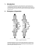
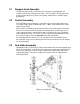
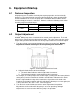
1. Introduction The GLM® DM7 metering pump is positive displacement, mechanically operated reciprocating diaphragm pump. Each pump consists of a power end and a process end separated by a Teflon faced diaphragm. Individual pumps will vary in appearance due to various liquid ends and accessories; however, the basic principles of operation remain the same. 2.
2.1 Reagent Head Assembly The typical reagent head assembly consists of reagent head, diaphragm, and suction and discharge cartridge check valves. This assembly is the only part of the pump to contact the process liquid; consequently, maintenance is critical to pump performance. 2.2 Control Assembly The GLM® DM7 pump incorporates a full motion style of stroke length adjustment. The stroke length setting is indicated by a (0% – 100%) scale located on the stroke adjustment assembly.
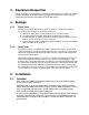
3. Equipment Inspection Check all equipment for completeness against the order and for any evidence of shipping damage. Shortages or damage must be reported immediately to the carrier and your authorized representative or distributor of GLM® DM7 pumps. 4. Storage 4.1.1 Short Term Storage of your GLM® DM7 pump for up to 12 months is considered short-term. The recommended short-term storage procedures are: a. Store the pump indoors at room temperature in a dry environment. b.
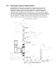
5.2 Piping System 1. All systems should include a pressure relief valve on the discharge side, to protect piping and process equipment, including the pump, from excess process pressures. An external relief valve is required! There should be no devices capable of restricting flow (such as a valve) located between the pump and the relief device. 2. Shutoff valves and unions (or flanges) on suction and discharge piping are recommended.
5.4 Discharge Pressure Requirements All GLM® DM7 metering pumps are designed for continuous service at the rated discharge pressure. If system suction pressure exceeds discharge pressure (a condition sometimes described as “pumping downhill”), flow would be generated (siphoning) in addition to that caused by the pump. This results in a reduction in accuracy and loss of control over the metering process.
6. Equipment Startup 6.1 Fastener Inspection All pump fasteners should be checked prior to pump operation, and occasionally during use. This would include reagent head mounting bolts, motor mounting bolts, and the hardware that secures the pump to its foundation. Most hardware can be checked simply to ensure it is not loose. However, utilize the following values when checking reagent head bolt torque: Reagent Head Bolt Torque Model Material # Bolts and size N-m In. - Lbs 8.5 75 Plastic (8) M10 * 1.
6.3 6.3.1 Oil Fill and Maintenance Oil Capacities It is recommended that adequate supplies of PULSALube oil be on hand for periodic changes and emergency requirements. The approximate amounts of oil required to fill the GLM® DM7 pump to specified levels are: Pump Capacity Gearbox, Model DM7 PULSALube EP Gear Oil Pulsafeeder Part No. NP980010-001 NP980010-002 NP980010-003 NP980010-004 6.3.2 2,500 ml (2.
6.3.3 Oil Changes The recommended oil change intervals are dependent upon the operating environment and level of pump usage, classified as follows: Normal service: Clean/dry atmosphere, an ambient operating temperature of 00 C to 400 C (320 F to 1040 F) and up to 2,000 annual operating hours. Severe Service: Humid atmosphere, an ambient operating temperature below 00 C (320 F) or 0 above 400 C (104 F), and over 2,000 annual operating hours.
6. Start the pump at the zero stroke length setting and slowly increase the setting to 100 to prime the pump. If this does not work, it will be necessary to fill the suction line. 7. Filling of the suction line will necessitate the use of a foot valve or similar device at the end of the suction line so that liquid can be maintained above the reservoir level.
6.5 Calibration Figure 7, sample flow calibration curve All metering pumps must be calibrated to accurately specify stroke length settings for required flow rates. A typical calibration chart is shown above. Although output is linear with respect to stroke length setting, an increase in discharge pressure decreases output uniformly, describing a series of parallel lines, one for each pressure (only two are shown).
7. Maintenance BEFORE PERFORMING ANY MAINTENANCE REQUIRING REAGENT HEAD OR VALVE (WET END) DISASSEMBLY, BE SURE TO RELIEVE PRESSURE FROM THE PIPING SYSTEM AND, WHERE HAZARDOUS PROCESS MATERIALS ARE INVOLVED, RENDER THE PUMP SAFE TO PERSONNEL AND THE ENVIRONMENT BY CLEANING AND CHEMICALLY NEUTRALIZING AS APPROPRIATE. WEAR PROTECTIVE CLOTHING AND EQUIPMENT AS APPROPRIATE. Accurate records from the early stages of pump operation will indicate the type and levels of required maintenance.
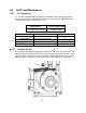
Figure 8, wet end components GLM® DM7 diaphragms do not have a specific cycle life; however, the accumulation of foreign material or debris sufficient to deform the diaphragm can eventually cause failure. Failure can also occur as a result of system over pressure or chemical attack. Periodic diaphragm inspection and replacement are recommended. Each user should perform regular inspections to determine the replacement interval that is appropriate to their system conditions.
7.1 Diaphragm Removal & Reinstallation 1. Adjust the stroke setting to 0% and disconnect the power source to the drive motor. 2. Relieve all pressure from the piping system. Take all precautions described under the WARNINGS on page 14, Section 7 to prevent environmental damage and exposure of personnel to hazardous materials. 3. Close the inlet and outlet shutoff valves. 4. Place a pan underneath the pump head adaptor to catch any liquid leakage. 5.
6. Remove all but one top reagent head bolt. Product will leak out between the pump head adaptor and reagent head as the bolts are loosened. 7. Remove the final bolt and rinse or clean the reagent head with an appropriate material. 8. Insert a screwdriver or similar tool through the oil fill hole and into the hole provided in the pushrod, this will keep the pushrod from turning as the diaphragm is removed.
12. Thread the diaphragm (clockwise) fully onto the shaft. When reinstalling a used diaphragm it is not necessary to maintain the previous orientation relative to the reagent head or pump head hole pattern. 13. Remove the screwdriver from the oil fill hole and replace the cap. 14. Install the reagent head bolts and tighten in an alternating pattern to ensure an even seating force. Torque to the values recommended in Section 6.1. 15.
7.3 Check Valves Most fluid metering problems are related to check valves. Problems usually stem from solids accumulation between valve and seat, corrosion of seating surfaces, erosion, or physical damage due to wear or the presence of foreign objects. The valve incorporates a ball, guide, and seat. Flow in the unchecked direction lifts the ball off the seat, allowing liquid to pass through the guide. Reverse flow forces the ball down, sealing it against the sharp edge of the seat.
7.4 Check Valve Removal & Reinstallation, Plastic Union-Nut type 1. Disconnect the power source to the drive motor. 2. Relieve all pressure from the piping system, and take all precautions necessary to prevent contamination to the environment and personnel exposure to hazardous materials. 3. Close the inlet and outlet shutoff valves. 4. Loosen the union nuts that hold the check valves in place. It is not necessary to completely remove the nut. 5.
7.5 Check Valve Removal and Reinstallation, Metal Tie-Bar type 1. Disconnect the power source to the drive motor. 2. Relieve all pressure from the piping system. 3. Take all precautions necessary to prevent contamination to the environment and personnel exposure to hazardous materials. 4. Close the inlet and outlet shutoff valves. 5. Loosen the suction valve tie-bar bolts (4) and spring the suction piping slightly away from the head, allowing liquid to drain.
Figure 14, Check valves, metal construction 22
7.6 Motor Removal & Reinstallation 1. Disconnect the power source to the drive motor. 2. Disconnect the motor wiring from the motor. 3. Remove the four bolts retaining the motor to the motor adaptor. Lift the motor upwards away from the pump. 4. Apply an anti-seize paste or lubricant to all bolts, setscrews, and keys before reassembling.. 5. Reinstall the motor in the reverse from removal. 6. Insert and tighten the four bolts removed in step 3. 7. Reconnect the motor wiring to the motor. 8.
8. Replacement Parts 8.1 KOPkit Program GLM® DM7 KOPkits contain all replacement parts normally used in a preventative maintenance program. (PULSAlube oil is also available separately for preventative maintenance programs. Refer to Section 6 – Equipment Startup). There is a specific KOPkit for every GLM® pump model. Each KOPkit is vacuum-packed for extended storage. All GLM® pumps have the KOPkit number identified on the pump nameplate and Pulsafeeder order documents.
8.3 KOPkit numbers by model: Pump Model Wetted Material Connection Type KOPkit number DM7 Polypropylene NPT / ISO / FLG KD7P DM7 31 6 NPT KD7A NOTES: (1) DM1 through 6 models are covered in a separate publication (2) Polypropylene KOPkits are identical as only balls and insert o-rings are supplied 9.
10. Troubleshooting DIFFICULTY Pump does not start No delivery Low delivery Delivery gradually drops PROBABLE CAUSE REMEDY Faulty power source Check power source Blown fuse, circuit breaker overload Replace - eliminate Broken wire Locate and repair Wired improperly Check diagram Process piping blockage Open valves, clear other obstructions Motor not running Check power source.
DIFFICULTY Delivery erratic Delivery higher than rated Noisy gearing, knocking Piping noisy Motor overheats PROBABLE CAUSE REMEDY Leak in suction line Locate and correct Product cavitating Increase suction pressure Entrained air or gas in product Consult factory for suggested venting Motor speed erratic Check voltage and frequency Fouled check valves Clean, replace if necessary Inadequate backpressure Increase discharge pressure to obtain a minimum pressure difference of 5 psi from suctio
11. Piping Accessories Pressure Relief Valves Pressure relief valves are designed to protect chemical feed systems from damage that may be caused by defective equipment or a blockage in the discharge line. These valves function to limit the pressure downstream of the pump. Field adjust the pressure relief valve to operate when the discharge pressure exceeds operating pressure by 10-15%. Pressure relief valve should always be adjusted to a setting below the maximum rated pressure of the pump.
12.
13.
® PULSA GLM MECHANICAL DIAPHRAGM METERING PUMP Bulletin #: IOM-GLM-DM7-001 A unit of IDEX Corporation 2883 Brighton Henrietta Town Line Road Rochester NY 14623 +1 (585) 292-8000 www.pulsa.com pulsa@idexcorp.