INSTALLATION OPERATION MAINTENANCE INSTRUCTION BULLETIN No. 680C Manufacturers of Quality Pumps, Controls and Systems ENGINEERED PUMP OPERATIONS 2883 Brighton Henrietta TL Road P.O. Box 22909 Rochester, New York, 14692-22909 USA Telephone (716) 292-8000 Fax (716) 424-5619 http://www.pulsa.
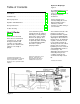
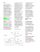
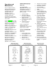
Table of Contents Hydracone Diaphragm Figure 2 How it Works . . . . . . . . . . . . . . . . . . . . . . . . . . . . . . . . . . . . . . . . . . . 2 The HYDRACONE elastomer diaphragm Figure No. 2 isolates product pumped from the plunger and pump mechanism. Installation Tips . . . . . . . . . . . . . . . . . . . . . . . . . . . . . . . . . . . . . . . . . 4 Start-Up Inspection . . . . . . . . . . . . . . . . . . . . . . . . . . . . . . . . . . . . . . 6 Operation and Maintenance . . . . . . . . . . . . .
Any leakage past the plunger, however slight, is replaced by the make-up valve which permits flow of replacement oil from the oil reservoir. Replacement is automatic because the oil loss allows the diaphragm to get out of phase with the plunger thus creating a vacuum ahead of the plunger during the suction stroke of the pump. The make-up valves are factory set.
Installation Tips Check The Shipment A standard PULSA Series shipment includes the pump, PULSAlube oil, wrenches, instruction and parts list packet and replacement parts if ordered. Unpack carefully, check packing list and make sure all parts are received. Check voltage of electric motor against the service to be used. Locating the 680C Pumps: PULSA 680C pumps are designed to operated under indoor atmospheric conditions. It is desirable to provide a hood or covering for outdoor service.
Piping: Pipe size and length are critical to proper operation of any metering pump. A restricted discharge or starved suction condition spells immediate failure to any metering pump installation. A separate brochure entitled "Designing a Successful Metering Pump Installation" is provided to assist Engineers responsible for piping system design. Copies are available upon request (Technical Sheet 304). Inlet piping must be at least equal in size to pump inlet connection.
Start-Up Inspection Every 680C metering pump is tested for correct capacity at maximum pressure capability of the hydraulic bypass valve before shipment. The diaphragm cavity is fully primed and remains so for shipment. For shipping purposes the gear and hydraulic reservoir oil have been removed. Sufficient fresh PULSAlube oil is included with the shipment for refilling the gear and hydraulic reservoirs. Warning 1. Do not run pump without oil. 2. Do not remove main gear box cover while pump is running. 3.
To Adjust Flow Rate; Figure B. The 680C PULSA pumps are provided with a micrometer knob adjustment for changing length of stroke while in operation or idle. NOTE: The external auto locking knob must be fully disengaged prior to adjustment. When adjustment is complete the lock will automatically engage to prevent drifting of the stroke setting. Turn adjustment knob clockwise to increase flow and counterclockwise to decrease flow. The adjustment knob is read directly in percent of stroke length.
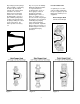
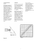
Figures D and E show two typical piping arrangements for performing pump calibration. It is desirable to calibrate from the suction side of the pump so the pump will be operating under actual or comparable discharge conditions. PULSA pumps supplied with automatic controls, either pneumatic or electronic, are accompanied by separate instructions on output adjustment and calibration. Check the capacity several times at three different stroke length settings and record them on linear graph paper.
Operation and Maintenance The preceding instructions have assisted you in proper installation and start-up of your 680C pump. The following sections are arranged to assist in maintaining proper pump operation and trouble shooting any problems that might develop during start-up or thereafter. HYDRACONE Diaphragm Inspection The HYDRACONE diaphragm is an elastomeric material which stretches on each displacement of the plunger. It can be damaged by the following: 1. 2. 3. 4.
13. Diaphragm can be removed from the reagent head by applying air pressure to one of the valve ports while blocking the other. Be sure diaphragm is directed away from personnel so that it does not strike the body when being expelled from the head. 14. Diaphragms which are punctured or show evidence of tearing or abrasion at the sealing edge should be replaced. If diaphragm shows evidence of hardening so as to be non-flexible it should be replaced. Repriming Hydraulic Systems on HYDRACONE Models 1. 2.
Hydraulic Make-up Valves Figure 12 Hydraulic make-up valves are designed to maintain the correct volume of oil in the hydraulic system between the piston and the diaphragm. No adjustment or attention is required, provided the oil is clean and free of moisture and chemical contamination. Since the valve operates only occasionally and with very little movement it is not considered a normal replacement item in a service schedule.
Lubricating Instructions PULSAlube is a custom blend oil with additives for lubrication and hydraulic transfer service. (For emergency requirements, a list of acceptable commercial oils is available). The diaphragm on the cover of the gear box assembly generally protects the oil from contamination for extended periods of time. A periodic six month check should be made for oil level and possible contamination.
Maintenance Parts Stock Ordering Parts Trouble Shooting Pulsafeeder offers a KOPkit which uses a group of recommended spares carried in stock for replacement due to normal wear. The Kit covers such items as diaphragm, diaphragm gaskets if used, inlet and discharge valve parts, a complete set of valve gaskets and hydraulic pump head gasket. The KOPkit part number for your pump is indicated on the nameplate. A sufficient quantity of PULSAlube oil should be on hand for periodic oil changes.
Trouble Shooting Chart Difficulty Probable Cause Remedy Pump Does Not Start 1. 2. 3. 4. 5. Coupling disconnected Faulty power source Blown fuse, circuit breaker Broken wire Wired improperly Connect and align Check power source Replace -- Locate overload Locate and repair Check diagram No Delivery 1. 2. 3. 4. 5. 6. 7. 8. Motor not running Supply tank empty Lines clogged Closed line valves Ball check valves held open with solids Vapor lock, cavitation Prime lost Strainer clogged Check power source.
Difficulty Delivery Higher Than Rated Probable Cause Remedy 1. Suction pressure higher than discharge pressure 2. Suction piping too small 3. Back pressure valvae set too low 4. Back pressure valve leaks Pump Loses Oil 1. 2. 3. 4. Diaphragm ruptured Leaky oil seal Cover gasket leaks Pump head gasket leaks Replace Replace Replace or tighten Replace -- tighten pump head bolts. Seal with permatex. Remove excess oil 5.
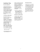
APPENDIX PULSAFEEDER ACCESSORIES I. PULSATROL INSTALLATION, OPERATION AND REMOVAL INSTRUCTIONS The PULSAtrol is a pneumatically charged diaphragm type chamber that continuously stores energy. Used on the inlet it will improve NPSHa (Net Positive Suction Head available) characteristics of the suction piping system. On the discharge line it will reduce dangerous peak pressures, eliminate shock waves and if of sufficient volume will reduce pulsating flow to almost linear.
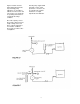
OPERATION (Charging the PULSAtrol) A. Discharge Installation The air side of the PULSAtrol must be precharged to approximately 50 percent of anticipated mean line pressure before placing on stream. This will permit the diaphragm to move to a neutral position between the chambers when operating. PROCEDURE Pre Charge Procedure for Discharge Installation 1. Calculate the precharge pressure Mean Line Pressure (PSIG) + Atmospheric Pressure Absolute Pressure (PSIA) x Precharge Percentage (80% Max.
II. DIAPHRAGM BACK PRESSURE VALVES Figure 14 Pulsafeeder diaphragm back pressure valves create a constant back pressure without chatter or cycling. A TFE diaphragm, offering maximum chemical protection and service life, seals spring and bonnet from product. This diaphragm seals directly on a replaceable seat. Be sure to install with fluid flow in direction of arrow on valve body. If arrow is missing from plastic valve body, install with flow exiting out center hole of valve body.
MAINTENANCE LOG Pump Model Serial # Gear Ratio Maximum Flow Piston Diameter Maximum Pressure KOPKit All the above information can be obtained from the pump nameplate. Refer to the Pump Specification Data Sheet for additional information.
CP 9/97 20 PRINTED IN USA