
Instruction Manual

10
13. Diaphragm can be 3. Connect inlet piping.
removed from the 4. With discharge line 8. Add PULSAlube oil to
reagent head by applying bypassed around front and rear oil
air pressure to one of the process or to drain, start reservoirs to bring oil
valve ports while motor and prime reagent level up to top of
blocking the other. Be head. partition.
sure diaphragm is 5. Set stroke length 9. After pump has run for
directed away from adjustment to maximum several hours, again
personnel so that it does stroke. check for any last traces
not strike the body when 6. If not already lose, of air at the bypass valve.
being expelled from the counting turns, loosen
head. the hydraulic bypass Check Valve
14. Diaphragms which are valve located at the top
punctured or show of the hydraulic system
evidence of tearing or to atmosphere and any Operating experience on
abrasion at the sealing air present will vent back thousands of installations has
edge should be into the gearbox oil indicated that many pump
replaced. If diaphragm reservoir as the troubles have to do with check
shows evidence of automatic make-up valve valves. Problems usually
hardening so as to be fills the piston/diaphragm stem from (a) an
non-flexible it should be chamber. Air bubbles accumulation of trash
replaced. will be evident at the vent between the valve and seat,
Repriming Hydraulic head in back of return seating surfaces, (c) erosion
Systems on HYDRACONE spring. from high velocity flow, or (d)
Models 7. When last traces of air normal physical damage after
1. Reassemble diaphragm retighten the bypass
and reagent head, valve the same number When inspecting the valves,
tightening all bolts of turns or to a desired separate the assembly and
securely and evenly. setting using a pressure examine the components for
2. Reassemble valve gauge in the process wear, damage or
housing, valves, seats line. Approximately a 1/2 accumulation of solids. A ball
and seat gaskets and turn more after process valve seat should have a
take care in inserting pressure setting has sharp 90 edge, free of any
gaskets that they are been reached will seat nicks or dents. Hold the ball
properly placed. Tighten valve. The valve can be firmly on the seat and
securely. set higher if desired but examine against a light. If
hole, top center of pump (b) corrosion which damages
have been expelled extended service.
do not exceed MAX. light is visible between the two
OPERATING then replace the seat and/or
PRESSURE indicated on ball.
the nameplate.
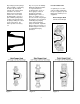
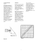
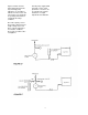
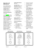
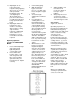
Figure 7, 8, 9 and 10
o
When reassembling after
cleaning or replacement be
sure to use new seals.