
Instruction Manual

3
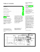
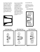
Figure 3. Figure 4. Figure 6.
Figure 2.
Figure 5.
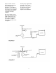
Any leakage past the plunger, Any excess pressure buildup Pressure Relief Valve
however slight, is replaced by within the hydraulic chamber
the make-up valve which or reagent head due to A separate process relief
permits flow of replacement accidental valve closure or valve should be installed in
oil from the oil reservoir. line stoppage is relieved the process piping to protect
Replacement is automatic through the automatic piping and sensitive process
because the oil loss allows hydraulic bypass valve. It equipment.
the diaphragm to get out of blows off oil under excess
phase with the plunger thus pressure ahead of the plunger Plastic Reagent Head
creating a vacuum ahead of back into the oil reservoir thus 3/8" Dia. Piston Design
the plunger during the suction terminating the pumping
stroke of the pump. The action and protecting the
make-up valves are factory pump mechanism. Hydraulic
set. bypass valves are factory set
at full design pressure unless
specified differently by
purchaser.