
Instruction Manual

7
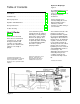
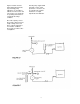
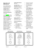
Figure B
To Adjust Flow Rate; Calibration: This is caused by
Figure B.
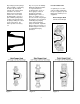
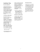
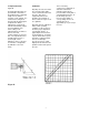
The 680C PULSA pumps are at room temperature with 7 Capacity at atmospheric
provided with a micrometer foot flooded head at full rated pressure will be nearly that of
knob adjustment for changing pressure. Any curves calculated displacement. As
length of stroke while in supplied by Pulsafeeder the discharge pressure
operation or idle. NOTE: The would be representative of increases there will be a
external auto locking knob this test and can only be used corresponding decrease in
must be fully disengaged prior as a guideline. capacity at a rate of
to adjustment. When approximately 1% per 100 psi
adjustment is complete the All pumps must be calibrated increase.
lock will automatically engage under actual operating
to prevent drifting of the conditions for the operator to
stroke setting. Turn know the proper adjustment
adjustment knob clockwise to for particular outputs. A
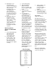
increase flow and typical displacement chart is
counterclockwise to decrease shown in Figure C. Note that
flow. The adjustment knob is output is linear with respect to
read directly in percent of micrometer settings but that
stroke length. These increase in discharge
indications can be converted pressure decreases output
to volumetric or weight units slightly and describes the line
by calibration conversion parallel to that at atmospheric
charts. pressure.
All pumps are tested on water and valve inefficiencies.
compression of hydraulic oil