Installation Operation Maintenance Instruction Bulletin #: IOM-680 IOM-680 Rev B.
Table of Contents 1. INTRODUCTION ..................................................................................................................................... 1 1.1 How Things Work .................................................................................................................... 1 1.2 Hydraulically Balance Flat Diaphragm Design ..................................................................... 1 1.3 Pump Head Assemblies ....................................................
4. OPERATION AND MAINTENANCE ............................................................................................................ 9 4.1 Diaphragm Inspection ............................................................................................................. 10 4.2 Repriming Hydraulic ............................................................................................................... 11 4.3 Piston and Diaphragm Alignment........................................................
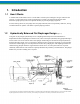
1. Introduction 1.1 How it Works A standard foot mounted motor drives a worm shaft at constant speed. Through worm gear reduction and eccentric, a reciprocating power stroke is transferred to a plunger. The length of the plunger stroke determines pump capacity and can be adjusted manually to provide pumping range from 0-100% of rating. However, this plunger does not pump chemicals, but an exceptionally stable oil*, having excellent lubrication qualities. This makes a perfect pumping medium. 1.
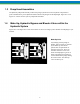
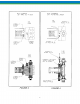
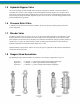
1.3 Pump Head Assemblies The hydraulic pump head assembly contains the plunger cylinder and various hydraulic components to protect and maintain a precise hydraulic balance between the plunger and the diaphragm. Figure No. 3 and Figure No. 4 shows various styles of pump head assemblies. 1.4 Make-Up, Hydraulic Bypass and Bleeder Valves within the Hydraulic System Figures No. 3 and Figure No. 4 show the locations of valves according to piston diameter and diaphragm style selected.
3
1.5 Hydraulic Bypass Valve Any excess hydraulic pressure buildup within the pump compression chamber or chemical end due to accidental valve closure or line stoppage is relieved through the hydraulic bypass valve. It blows off oil under excess pressure ahead of the plunger back into the oil reservoir thus terminating the pumping action and protecting the pump mechanism. Hydraulic bypass valves are factory set at full design pressure unless specified differently by purchaser. 1.
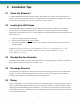
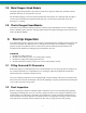
2. Installation Tips 2.1 Check the Shipment A standard Pulsafeeder shipment includes the pump, PULSAlube oil, wrenches, instruction and parts list packet as well as replacement parts if ordered. Unpack carefully, check packing list and make sure all parts are received. Check voltage of electric motor against the service to be used. 2.2 Locating the 680 Pumps PULSAFEEDER pumps are designed to operate under indoor atmospheric conditions. It is desirable to provide a hood or covering for outdoor service.
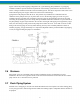
Figure A shows the preferred piping configuration for a good metering pump installation. A god piping installation addresses present and future requirements of the metering system. Plan for shut off valves and unions or flanges installed on both the suction and discharge lines. This allows inspection of the check valves without draining long runs of pipe. Install a tee in the suction and discharge piping between the pump and shut off valves.
2.8 Metal Reagent Head Models The metal reagent head assembly is provided in several alloys. Piping of similar alloy should be selected. Dissimilar materials can cause galvanic corrosion. Do not backweld piping to the valve housings without first removing the valve housings from the pump as excessive heat can damage the reagent head and other parts. Tie bars must be positioned on the valve housing before welding. 2.
3.3 Start-up Since the hydraulic oil system is primed at the factory, priming the process system is all that should be necessary to produce flow. If the hydraulic system has inadvertently been dumped due to start up with restricted suction or discharge conditions or improper adjustments to compensator or bleed valves, repriming procedures under the maintenance section may have to be followed before pump calibration can begin. 3.4 Priming Process Head 1.
3.5 To Adjust Flow Rate (Figure B) The 680 Pulsafeeder pumps are provided with a lock-in place micrometer knob adjustment for changing length of stroke while in operation or idle. Push in on locking device and turn adjustment knob clockwise to increase flow and counterclockwise to decrease flow. These indications can be converted to volumetric or weight units by calibration conversion charts.
4.1 Diaphragm Inspection (Figure 3 & 4) Pulsafeeder TFE plastic or metal diaphragms are not subject to stress fatigue and do not fail from repeated flexure. However, long-time accumulation of foreign material or entrapment of hard, sharp particles between the diaphragm and the dish cavity can eventually cause premature damage. Periodic inspection of the diaphragm is desirable, especially if the product pumped carries large particles or trash.
BOLT TORQUE RECOMMENDATIONS FOR MODELS WITH METAL HEADS AND PLASTIC DIAPHRAGMS (1) (2) Piston Dia. .250-.500 .625-1.50 Reagent Head Bolts 240-300 in. lbs 276-345 kg.m 60-70 in. lbs. .69-81 kg.-m Tie Bar Bolts 45-65 in. lbs. .52-75kg.-m 25-45 in. lbs. .29-52 kg.-m (1) Metal diaphragm models/reagent head bolts can be tightened to normal range compatible with bolt sizes. Tie bar bolt torque same as for plastic diaphragm models.
4.4 Check Valves (Figure 8, 9, 10 & 11) Operating experience on thousands of installations has indicated the many metering pump troubles have to do with check valves. Problems usually stem from (a) an accumulation of trash between the valve and seat, (b) corrosion which damages seating surfaces, (c) erosion from high velocity flow, or (d) normal physical damage after extended service. When reassembling after cleaning or replacement be sure to use new seals.
4.6 Adjustable Valves (Figure 12) This valve is factory set and operator adjustable. Under normal circumstances adjustment is not necessary. Normal victory setting allows two threads to show from end of threaded shaft to locking nut. The valve requires no routine maintenance and is not considered a normal replacement item. In some situations it is necessary to adjust the valve. If sprint tension is too tight, this condition is signaled by a gradual loss in pump capacity.
of large piston fast stroke rate pumps, the dumping pressure is an instantaneous pressure generally experienced only in the first discharge stroke of the pump since the make-up valve cannot replace the displacement of the piston in one stroke. It is unusual for a hydraulic bypass valve to operate during normal pump operation. The following conditions will cause bypass pump operation. 1. Excessive pressure buildup in the process which the pump is injecting into. 2.
4.9 Manual Bleed Valve (Figure 15) The manual bleed valve is used in small piston models where oil movement and hydraulic instabilities are minimal. To operate this valve, loosen the valve a slight amount until the oil is seen coming out. Leave the valve loosened for a few strokes of the pump and then retighten. 4.
4.11 Oil Capacity The standard 680 metering pump requires approximately one quart of PULSAlube oil to fill both chambers and prime hydraulic pump head. PULSAlube oil is available in one quart bottles, one gallon bottles, 5 gallon pails or 55 gallon drums. 5. Storage Instructions 5.1 Short Term Storage of PULSA Series pumps for up to 12 months after shipment is considered short term. Under this condition the recommended storage procedures are as follows: 1.
5.3 Maintenance Parts Stock- KOPkits® Pulsafeeder offers a KOPkit which is a group of recommended spares carried in stock for replacement due to normal wear. The Kit covers such items as diaphragm, diaphragm gaskets if used, inlet and discharge valve parts, a complete set of valve gaskets and hydraulic pump head gasket. The KOPkit part number for your pump is indicated don the nameplate. A sufficient quantity of PULSAlube oil should be on hand for periodic oil changes. 5.
6. Troubleshooting Difficulty Probable Cause Remedy Pump does not start 1. 2. 3. 4. 5. Coupling disconnected. Faulty power source Blown fuse, circuit breaker Broken wire Wired improperly. 1. 2. 3. 4. 5. Connect and align Check power source. Replace-locate overload. Locate and repair. Check diagram. No Delivery wiring diagram. 1. 2. 3. 4. 5. Motor not running. Supply tank empty. Lines clogged. Closed lined valves. Ball check valves held open with solids. Vapor lock, cavitation. Prime lost.
Difficulty Probable Cause Remedy Delivery Erratic 1. 2. 3. 4. 5. Leak in suction line. Product cavitating. Entrained air or gas in product. Motor speed erratic. Fouled check valves. Delivery Higher Than Rated 1. Suction pressure higher than discharge pressure. 3. Back pressure valve set too low. 4. Back pressure valve leaks. 1. Install back pressure valve or consult factory for piping recommendations. 2. Increase pipe size-install PULSAtrol pulsation dampener at pump in discharge line. 3.
Difficulty Piping Noisy Probable Cause Remedy 1. Pipe size too small. 2. Pipe runs too long. 3. Surge chambers full of liquid. 4. No surge chambers used. Motor Overheats pump design 1. 2. 3. 4. Pump overloaded Oil too viscous Low voltage Loose wire 1. Increase size of piping, install PULSAtrol. 2. Install PULSAtrol in line. 3. Recharge with air or inert gas, replace diaphragm and recharge 4. Install PULSAtrols-pulsation dampeners 1. 2. 3. 4.
7.2 Operation (Charging the PULSAtrol) PROCEDURE: Pre-Charge Procedure for Discharge Installation 1. Calculate the precharge pressure: Mean Line Pressure (PSIG) + Atmospheric Pressure Absolute Pressure (PSIA) x Precharge Percentage (80% Max) Pressure Absolute -Atmospheric Pressure Precharge Pressure (PSIG) =Precharge Pressure 2. 3. 4. 5. 6. Isolate PULSAtrol from line. Carefully drain off process fluid by opening a drain valve (see recommended piping arrangement).
8. Diaphragm Back Pressure Valves (Figure 17) Pulsafeeder diaphragm back pressure valves create a constant back pressure without chatter or cycling. A TFE diaphragm, offering maximum chemical protection and service life, seals spring and bonnet from product. This diaphragm seals directly on a replaceable seat.. Be sure to install with fluid flow in direction of arrow on valve body. If arrow is missing from plastic valve body, install with flow exiting out center hole of valve body.
23 IOM-680 0922-Rev B