
Manual

10
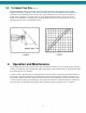
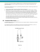
4.1 Diaphragm Inspection (Figure 3 & 4)
Pulsafeeder TFE plastic or metal diaphragms are not subject to stress fatigue and do not fail from repeated
flexure. However, long-time accumulation of foreign material or entrapment of hard, sharp particles between the
diaphragm and the dish cavity can eventually cause premature damage.
Periodic inspection of the diaphragm is desirable, especially if the product pumped carries large particles or trash.
To remove the diaphragm, the first four steps are the same for plastic and metal diaphragms.
1. Remove all pressure from the piping system.
2. Close the inlet and outlet shut-off valves.
3. Break the union or flanges on the piping.
4. Arrange to catch and properly dispose of the oil and product leakage that will occur when disassembling head
and valving.
5. Remove the inlet check valve to drain reagent head and cavity. Use extreme caution if product is hazardous
and wear proper protective clothing.
For plastic diaphragms, follow Steps 6 through 10. For metal, follow Steps 11 through 15.
6. Remove reagent head bolts and rinse the head in water or a compatible liquid.
7. Flat disc style diaphragms in TFE material which remain attached to the reagent head can be removed
undamaged by forcing compressed air into the inlet port while plugging the discharge port. Diaphragms
which remain attached to the hydraulic pump head can be removed undamaged by rotating the piston by hand.
8. If the diaphragm shows no evidence of damage, there is no need to replace it. A slight warped condition is
normal and will not require replacement of the diaphragm.
9. On models which have an insert dish plate, make sure the dish plate is reset in the pump head with the cavity
on the diaphragm side and one of the four holes closest to the outer edge positioned at the top to permit air to
bleed out of the cavity when priming.
10. Some Pulsafeeder plastic diaphragms incorporate an integral “O” ring design. Follow torque restriction in
table on the following page. Simply tighten to bolt strength limit. On other models, where there is no “O”
ring, the diaphragm must be compressed to form a seal. Be careful to follow the torque limits in the table
(page 10). MODELS WITH PLASTIC HEAD AND VALVES MUST BE TIGHTENED BY HAND ONLY
TO AVOID DISTORTION OF PARTS.
The following steps apply to metal diaphragms:
11. As the diaphragm is sealed by “O” rings, or gaskets, at bolt the pump head and reagent head, leakage of both
oil and product pumped can occur simultaneously when the reagent head bolts are loosened. It is, therefore,
desirable to remove the inlet check valve to drain the reagent head and cavity. Proceed with care if the
product is hazardous.
12. When removing the reagent head bolts, leave two bottom bolts in place but back them out until the diaphragm
is exposed at the top. Pick out the diaphragm with needle nose pliers.
13. If the diaphragm shows damage, replace it.
14. If the “O” rings are extruded or cut, replace them. On models with flat gaskets, replace the gaskets each time
the head is removed. Make sure gaskets are properly centered on serrations located on the pump and reagent
head. Hold the gaskets in place with an adhesive. DO NOT COMPLETELY COAT THE GASKETS AS
THIS WILL FILL SERRATIONS WITH COMPUND AND IMPAIR SEALING.
15. Before reassembly, make sure all faces of the reagent head and pump are clean.