
Manual

11
BOLT TORQUE RECOMMENDATIONS
FOR MODELS WITH METAL HEADS AND PLASTIC DIAPHRAGMS (1) (2)
Piston Dia. Reagent Head Bolts Tie Bar Bolts
.250-.500
.625-1.50
240-300 in. lbs 276-345 kg.m
60-70 in. lbs. .69-81 kg.-m
45-65 in. lbs. .52-75kg.-m
25-45 in. lbs. .29-52 kg.-m
(1) Metal diaphragm models/reagent head bolts can be tightened to normal range compatible with bolt sizes. Tie bar bolt
torque same as for plastic diaphragm models.
(2) DO NOT use these torque ratings for models with plastic reagent head and valve housings. Bolts on these models
should only be hand tightened for adequate seal at their lower pressure rating.
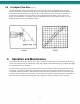
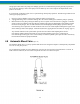
4.2 Repriming Hydraulic (Figure 3 & 4)
1. Reassemble diaphragm and reagent head, tightening all bolts securely and evenly. Use reliable torque wrench
to valves indicated.
2. Reassemble valve housing and take care in inserting gaskets that they are properly positioned. Replace valves,
seats and seat gaskets incorrect orientation for direction of flow (see Figure 8-11) and tighten securely.
3. Connect inlet piping.
4. With discharge line bypassed around process or to drain, start motor and prime reagent head.
5. Set stroke length adjustment to maximum stroke.
6. Stop the pump and remove the manual bleed/auto bleed valve assembly from pump head.
7. Place a plastic pipette (i.e. turkey baster) in the manual bleed/auto bleed valve hole of the pump head. Fill
pipette with oil being used in gearbox.
8. Start the pump. As the pump operates each suction stroke of the pump will draw in oil from pipette and each
discharge stroke will expel air from the pump head.
9. Add oil to pipette as necessary until no more air is expelled from the pump head and oil is moving up and
down pipette with piston movement.
10. Shut down the pump and manually retract the piston to full rearward position. (This may be done by
removing coupling cover and manually turning motor shaft.)
11. Remove the pipette and replace the manual bleed/auto bleed valve assembly.
4.3 Piston and Diaphragm Alignment
12. Manually rotate motor shaft until piston is in full forward position.
13. If piston does not set up before full forward position is obtained then pump piston and diaphragm is phased.
14. If piston set up at some point prior to achieving full forward position then loosen up bypass valve setting
(keeping track of the number of turns) until piston slips forward forcing excess oil from the pump head
through the bypass valve. Move piston to full forward position.
15. Retighten bypass valve to previous setting, but do not exceed MAX OPERATING PRESSURE indicated on
pump nameplate.
16. Hydraulics is primed and piston is phased with diaphragm.
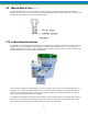
17. Add PULSAlube oil to front and rear reservoirs to bring oil level up to top of partition.
18. After the pump has run for several hours, again bleed manual air vent for any last trace of air.