Installation, Operation & Maintenance Instruction Bulletin No. PR- IOM - XPRC-0301-C Manufacturers of Quality Pumps, Controls and Systems ENGINEERED PUMP OPERATIONS 2883 Brighton-Henrietta Townline Road Rochester, New York, 14623 Telephone (585) 292-8000 Fax (585) 424-5619 www.pulsa.com pulsa@idexcorp.
DLC-XP/RC™ FACTORY SERVICE POLICY Your DLC–XP/RC™ is a state of the art microprocessor-based stroke length control device for use with PULSAR® Diaphragm Metering Pumps. It includes extensive on-board diagnostics. If you are experiencing a problem with your DLC–XP/RC, first review the diagnostic menu, then consult the trouble shooting guide.
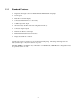
Table of Contents 1. INTRODUCTION ..................................................................................................................................... 1 1.1 Description .............................................................................................................................. 1 1.1.1 Standard Features........................................................................................................... 2 2. SAFETY CONSIDERATIONS .......................................
6.1.12 Wrapping up..................................................................................................................... 24 7. GENERAL OPERATION .......................................................................................................................... 25 7.1 Calibration................................................................................................................................ 25 7.1.1 Pump Flow Calibration....................................................
1. Introduction The DLC–XP/RC is a microprocessor based stroke length control device for use with the PULSAR diaphragm metering pump. It has been designed with many advanced features that allow the PULSAR to operate in a wide variety of industrial environments. This instruction manual covers the DLC–XP/RC - Digital Stroke Length Controller for NEMA 7 installations. Refer to Table 1 for the specific standard features and options for your model.
1.1.1 Standard Features • Digital stroke length control for PULSAR and SHADOW model pumps • User keypad • Back-lit 2 x 16 LCD display • Solid state PULSAR motor control relay • 4-20mA input and output • 10-Year battery backed clock and configuration memory • Solid state digital outputs • Drum level / Remote start input • PULSAlarm® Leak Detection interface • Diagnostics built into software Security states may be activated to prevent unwanted tampering.
2. Safety Considerations The DLC-XP/RC is a sophisticated microprocessor based controller for use only with PULSAR diaphragm metering pumps. It yields tremendous control capacity -- electrical, mechanical and (in conjunction with the PULSAR pump) hydraulic in nature. In consideration of SAFETY, the user should be mindful of this relative to his/her safety, that of co-workers and of the process environment.
3. Equipment Inspection Check all equipment for completeness against the order and for any evidence of shipping damage. Shortages or damage must be reported within 30 days of receipt of this equipment to the freight carrier and your PULSAFEEDER Representative. 4. Storage Instructions The DLC-XP/RC can be successfully stored for extended periods. The key to this success is control of temperature and humidity. 4.
5. Installation 5.1 Location IMPORTANT! Review the Safety section prior to installing the DLC-XP/RC. This section contains important information required to properly install and operate the equipment in an industrial environment. The site selected for the installation of your DLC-XP/RC is largely dependent on that of the PULSAR metering pump. Review the PULSAR Installation Operation Maintenance Instruction Manual provided with your PULSAR metering pump.
AVOID LOCATIONS WHERE THE DLC-XP/RC WOULD BE SUBJECTED TO EXTREME COLD OR HEAT [LESS THAN -18° CELSIUS (0° FAHRENHEIT) OR GREATER THAN 40° CELSIUS (104° FAHRENHEIT)] OR DIRECT SUNLIGHT. FAILURE TO OBSERVE THIS WARNING COULD DAMAGE THE DLC-XP/RC AND VOID ITS WARRANTY. 5.2 Installation Notes 1. The DLC-RC is a microprocessor based controller that uses static sensitive CMOS components.
5.3 Getting Started The field wiring terminals of the DLC-XP are accessed by removing the its cover. Remove the 13 retaining screws (Phillips head screw driver required). Refer to Figure 2. The field wiring terminals of the DLC-RC are openly visible on the chassis. Figure 2 – Accessing the Field Wiring board The DLC-XP cover has the Serial Number Tag on it. Please keep the cover with the DLC-XP from which it was removed. The DLC-XP is marked internally with the Serial Number.
5.3.1 Finding your way around the DLC-XP and DLC-RC Field Wiring Boards. The electrical connections are segregated on the Field Wiring Boards. On the DLC-XP, the High Voltage connections are near the conduit ports, the low voltage connections are furthest away from them. On the DLC-RC, the high voltage connections are on the right half of the board while the low voltage connections are on the left. Refer to the Field Wiring Board map in Figure 3 for specific connection and fuse locations. Figure 3.
5.4 Control Connections The DLC-RC is attached to the DLC-XP through one 10 conductor shielded cable. This cable transmits the encoder information from the DLC-XP to the DLC-RC -- allowing the DLC-RC to know the position of the stroke adjustment shaft at all times. Additionally this cable transmits the synchronous motor control and power signals from the DLC-RC to the DLC-XP. This allows the DLC-RC to change the position of the stroke adjustment shaft.
Figure 4. Control Connections 5.5 High Voltage Connections There is only one high voltage connection to be made on the DLC-XP: the supply power (J1). On the DLC-RC, there are only three high voltage connections: the supply power (J1), the PULSAR motor starter relay load (J3), and the Alarm Relay Load (J2). Only the supply power and PULSAR motor starter relay load connections are required. Refer to Figure 5 for connection location. Figure 5.
5.5.1 Supply Power The DLC-RC requires one connection to an external power source. It uses this same connection to power its own supply, the motor starter relay (external) and the alarm relay output. The user must be mindful of these external loads when sizing the branch circuit. The DLC-RC power supply and attached PULSAR motor starter relay (external) are not fuse protected. The user is responsible for correctly sizing the protection element (i.e., fuse or circuit breaker at the distribution panel).
THE DLC-RC USES SOLID-STATE RELAYS FOR IT'S HIGH VOLTAGE OUTPUTS (I.E., MOTOR AND ALARM). IN THE 'OFF' STATE, THESE DEVICES TYPICALLY LEAK 20-30MA OF CURRENT AT THE SUPPLY VOLTAGE! THE SUPPLY POWER MUST BE DISCONNECTED AT THE MAIN BEFORE WORKING ON ELECTRICAL CONNECTIONS. Wire the PULSAR motor to the motor starter in accordance with the starter manufacturer's instructions. Alternately, the three-phase logic output may be used for most solid-state relay control devices.
5.6.1 Analog Input (DLC-RC) The Analog Input is used for remote control of the PULSAR flow. The input accepts current inputs anywhere in the range of 0-25mA (e.g., 4-20mA) provided the 'span', (the difference between the High and Low value), is greater than 2mA. Voltage signals in the 0-5 volt range are accepted but displayed as current during Analog Input calibration. Split-ranging, reverse acting, and ratio control are accomplished in the calibration routine. No hardware adjustments are required.
5.7 Low Voltage Output Connections The DLC-XP control offers one Analog (e.g., 4-20mA) output, and two Transistor-based digital ouputs. The Low Voltage Output connection block is labeled J5 'OUTPUT' (refer to Figure 7). It contains three-pairs of outputs: Analog, Alarm and Motor Control Signal. The Transistor based Dry Contact output is optically isolated. It is not self-powered to achieve total isolation. The external device must supply and detect a return voltage level.
5.7.2 Alarm and Motor Status Outputs (DLC-RC) The Alarm and Status outputs are solid state transistor type. Logic HIGH indicates an ON condition while logic LOW indicates an OFF condition. They are commonly used to indicate an alarm status and run status to external control equipment (i.e., PLC, PC or other digital controllers). These outputs are limited to switching a maximum of 24 VDC. Refer to Figures 7 and 8. Figure 8. Schematic, Transistor based Alarm Output.
5.8 Fuse Replacement Although Fuse replacement is not a part of normal installation, it is often likely that fuse failure will result from improper wiring. The DLC-RC uses a total of 7 user replaceable fuses: 1 for the alarm relay output, 2 for each of the Analog Input and Output Channels.
6. Start Up Instructions 6.1 Overview Once all electrical connections have been made, your DLC-XP/RC is ready for Start-up. This can be completed in 9 simple steps. WHEN POWER IS SUPPLIED TO THE UNIT, LINE VOLTAGE IS PRESENT ON THE FIELD WIRING BOARDS OF BOTH THE DLC-XP AND DLC-RC EVEN WHEN THE MOTOR IS OFF. Display Keypad Pump Motor DLC-RC Serial Number Tag Wiring Cover DLC-XP Conduit Adaptor Figure 12 – Key DLC–XP/RC start-up elements DURING START-UP, IT IS NECESSARY TO START THE PUMP MOTOR.
6.1.1 User Interface Familiarization. There are four key elements that will be useful in starting-up the DLC: the Display, the Keypad, the DLC-XP and the Pump Motor. Refer to Figure 12 to familiarize yourself with the location of these items before proceeding. Figure 13 – Keypad 6.1.1.1 Display This is a 2 line by 16 character alpha-numeric Liquid Crystal Display (LCD) located above the keypad. It is back-lit with a yellow-green light source for easy viewing in dark areas.
This key is used to activate the [BATCH] processing menu. Press the [CAL] key to activate the Calibration menu for Flow and Analog Signals. The [MODE] key is used to change the operating mode of the DLC. For example, press once to change from MANUAL to ANALOG. Press a second time to change from ANALOG to MANUAL. 6.1.1.3 Actuator (DLC-XP): The Actuator or DLC-XP is mechanically attached to the PULSAR. It drives the stroke length adjustment mechanism.
6.1.3 Confirm Correct Incoming Power Double check that the DLC-XP cover is on and tightened down. Apply power to the DLC-XP first. Its proper operation will be confirmed when power is applied to the DLC-RC. When shutting down the DLC, turn the power to the DLC-XP off after power has been removed from the DLC-RC. Applying power to the DLC-RC will cause its display back-lighting to 'glow' with a yellow-green light.
At this time, the actual message is un-important, the characters should be visible and form a reasonable message. If the display is blank (no-characters) then the display contrast must be adjusted. This can be accomplished by pressing and holding [MENU] while simultaneously pressing [UP]. This will darken the display. Be patient! You may have to hold both keys down for as long as 30 seconds before the characters will become visible.
6.1.7 Menu Factory Re-Initialization: If the user interface is functioning properly, Factory Re-Initialization can be found in the Configure Menu. Perform the following steps: 1. Apply power to the unit. Wait for the {SELF-TEST} display to disappear. The unit should display a standard power on screen (refer to Figure 13). 2. Press [MENU]. The display will show the first menu item {DIAGNOSTICS}. 3. Press [DOWN] one time. The {FACTORY DEFAULTS} menu item should appear.
6.1.9 Confirm Proper DLC-XP Operation. To confirm that your DLC-XP is properly wired to your DLC-RC it is necessary to cause the DLCXP/RC to perform a zero calibration. Quite often when installing a DLC-XP/RC the unit will perform a zero calibration when it is first powered up (refer to Figure 17). DLC-XP CHECK POWER or PLEASE WAIT TESTING ENCODER or TURN MOTOR ON TESTING ENCODER Figure 17.
6.1.11 Calibration (1-point). Your DLC-XP/RC is factory calibrated at rated flow and pressure (1-point). Nevertheless, you should always perform a calibration with the PULSAR DLC-XP/RC installed in your system. In addition, a flow calibration will confirm that the DLC-XP is communicating properly with the DLCRC. The only item required to calibrate your DLC-XP/RC is a means to measure the output of the pump (i.e., calibration column, graduated cylinder, etc.).
7. General Operation This section covers the General Operation of the DLC as it relates to software. It includes detailed instructions and example screens to aid the user. The default values of the DLC have been factory set. The user can over-ride these settings to tune the DLC to his/her particular needs. 7.1 Calibration The DLC can be calibrated for Flow, Analog Input and Analog Output.
4. CHANGE CONSTANTS. Press [UP] until {CALIBRATION / CHANGE CONSTANTS} appears. This option is used to set the slope and Y-intercept in the equation that describes the linear calibration curve: y = ax + b. Where 'a' is the slope and 'b' is the Y-intercept. The input to this equation (i.e., x) is given in percent (%). The output (i.e., y) uses the currently displayed unit for flow. The units for the constants are given on screen.
The display is now displaying the current stroke setting (e.g., 100%), and the amount of fluid discharged from the pump the last time this operation was performed (e.g., 26.4157 Gallons). Based on this information, fill the calibration column in the system to the proper level to avoid running the pump dry during calibration. 9. When you are ready, press [ENTER]. This will start the pump motor for a period of 60 seconds. The display will show a 60 second timer and its count down toward 0 seconds.
Send the low analog signal to the DLC – XP (0 mA, 4 mA, 1 mA or 1 volt) from the control room. Refer to Section 5 – Installation: Low Voltage Input and Figure 6 for wiring instructions. It is highly recommended that you use the actual signal the DLC – XP will be receiving in order to properly configure the settings. The DLC – XP will display it's interpretation of the received signal. Do not be alarmed if the signal does not match the instrument. For example, your instrument is generating 4.
7.1.3 Reverse Acting Analog Input Signal Calibration To set up a reverse acting application, follow the above Analog Input Calibration procedure with the following changes to step 3 and 4: 1. In step 3, when the display requests the minimum analog signal value (0%), the user should send the DLC – XP the high analog signal value (20 mA, 10 mA or 5 volts). INPUT ANALOG MIN 0% = XX mA Send High (20mA) Signal The DLC – XP will digitally store this as the 0% analog input signal value.
4. The DLC – XP will prompt you to accept the analog output calibrated values. CONFIRM CHANGES? YES Press [ENTER] to accept the calibration. If you do not want to accept, press [UP] and then [ENTER]. The display will return to the standard operating mode. 7.2 Menu The default values and menus of the DLC – XP Stroke Length Controller have been factory set, but you will want to configure the DLC – XP to meet your specific application. The [MENU] key activates the Configuration Sub-menu system.
b) Press [UP] to scroll to the next sub-menu. If the analog signal failed (i.e., it went outside of its calibrated range or fell below 0.3mA at a rate of 2.2mA per second), a failure would be detected and logged. DIAG MENU 2/11 DIAG MENU 2/11 or ANALOG IN: OK ANALOG IN: FAIL c) Use [UP] to scroll to the next sub-menu. If serial communications fail, a failure would be detected and logged. DIAG MENU 3/11 DIAG MENU 3/11 or DIGITAL: OK DIGITAL: FAIL d) Use [UP] to scroll to the next sub-menu.
You can access a sub-menu from the above screen by pressing [ENTER] if a circuit failure has occurred. The lower level menus show more descriptive circuit information. The DLC – XP performs a self-test at power-up. The values in the menus shown below are updated during power-up. Use [UP] to scroll between sub-menus.
7.2.2 Set Time and Date The clock/calendar is essential to the proper operation of the batching system and proper error time stamping. The clock should be set at installation time. It can be configured to operate without any additional maintenance in most time zones. 1. Press the [MENU] key, then press [UP] until the –MENU–/SET TIME & DATE is displayed: –MENU– SET TIME & DATE Press [ENTER] to access the Set Time and Date sub-menu. 2.
8. The DLC prompts the user to accept the date programmed in the above referenced steps, {CONFIRM CHANGE}. Press [ENTER] to accept. If you do not want to accept the new inputs, press the [UP] arrow to scroll to "NO" and press [ENTER]. CONFIRM CHANGE? YES 9. The display will return to the main {SET TIME & DATE} menu. 7.2.3 Analog Signal Failure Set Up This sub-menu allows the user to set up the DLC – XP response if the analog signal fails.
The display prompts the percent of flow as the default setting. Enter the new value using [UP] and [DOWN]. Press [ENTER] to accept this value and the cursor moves to the next position. Continue to use the arrow keys and press [ENTER] to accept your selections. SIGNAL DEFAULT 000.0% FLOW 3. Pressing [ENTER] after configuring any of the previous steps (a-d) accepts your selection and will additionally open an {ERROR MESSAGE / …..} screen.
4. The display prompts if the alarm relay should be triggered. LEAK DETECTION LEAK DETECTION or ALARM RELAY? NO ALARM RELAY? YES Press [ENTER] to accept the default of NO. If you want the alarm relay to active if a leak is detected, press [UP] to scroll to {YES} and press [ENTER]. The display returns to the {MENU / LEAK DETECTION} screen. 7.2.5 Level Switch Failure Set Up This sub-menu allows the user to configure the DLC – XP to interact with a single point level sensor.
5. The display will then prompt for the motor status when the Level Switch input trips: LEVEL SWITCH MOTOR OFF? NO Press [ENTER] if you DO NOT want the PULSAR motor to turn off when the input is sensed. Go to step 7. 6. If you do want to the PULSAR motor to shut off is a low level is sensed, press [UP] to scroll to {YES}. Press [ENTER]. LEVEL SWITCH MOTOR OFF? YES 7. The display prompts you for the alarm relay status should Level Switch input trigger.
Press [ENTER} to accept the {DISABLED} setting. The display will return to the {– MENU – / OVER TEMPERATURE} screen. – MENU – OVER TEMPERATURE 7.2.9 Power Failure Set Up This sub-menu allows you to configure the way the DLC–XP/RC reacts to a power outage. During the power up stage, your system can either: − Return to settings that were active when the pump lost power, or − Shut the motor off. A power outage is defined as the loss of power when ever the DLC is not in {MOTOR OFF} state. 1.
7.2.11 Analog Mode Use the Analog Mode setting to activate the analog input. If you are not using the analog input, setting Analog Mode to Inactive will prevent errant operation if [MODE] is pressed accidentally. 1. Press [MENU]. Press [UP] seven times until the screen {-MENU- / ANALOG MODE} is displayed. –MENU– ANALOG MODE Press [ENTER] to continue to configure the analog mode. 2. Press [UP] and the {INACTIVE} option is displayed.
1. Press [MENU]. Press [UP] eleven times until the screen {MENU / SECURITY} appears. –MENU– SECURITY Press [ENTER] to continue to program the Security sub-menu. 2. The type of security available appears flashing on the display. a) If no password security protection is desired, press [ENTER] and go to step 5. SECURITY TYPE OFF b) Press [UP] and the {TAMPER PROOF} option will appear. If complete tamper proof security of all settings is required, press [ENTER] and go to step 3.
3. The decimal position screen is displayed. Use [DOWN] to move the decimal position one place to the left. For example, the screen displays 9.999, pressing [DOWN] causes the display to change to 0.9999. When the decimal position satisfies your needs press [ENTER] to accept. e.g. 0.9999 e.g. 9.999 Press [DOWN] DECIMAL POSITION DECIMAL POSITION 4. The display returns to {-MENU- / DECIMAL FORMAT}. 7.2.14 Contrast Adjust The DLC contrast can be adjusted to a desired setting. 1. Press [MENU].
7.2.17 Factory Default All of the DLC settings can be returned to factory defaults. 1. Press [MENU] and then [UP] sixteen times until the {MENU / FACTORY DEFAULTS} appears flashing. –MENU– FACTORY DEFAULTS Press the [ENTER] key to continue through the factory defaults sub-menu. 2. The display prompts you to not reset all the settings to the factory defaults. FACTORY RESET? NO If this is not desired, press [ENTER] and go to step 4.
7.6 Batch The DLC is capable of controlling up to three different batch programs. The batches operate in two modes: One Time Only and Repeating. All batches are based upon clock time. 7.6.1 One Time Only The One Time Only batch will start at a user specified time and run for a user specified duration. 7.6.2 Repeating A Repeating Batch will start at a specified time and run for a specified duration. It stop for a specified period of time and then repeat the run time. This will continue indefinitely.
7.6.3.1 Activating Batches 1. Press [BATCH], to enter the batch set-up menu.. 2. The display will come up as {BATCHES / ACTIVE} or {BATCHES / INACTIVE}. Press the [UP] arrow to change the batch system to {ACTIVE}. Press [ENTER] to continue on to the batch submenu. You have now activated the batching system. If any pre-configured batches are scheduled to start they will start immediately. 3. The display shows {EDIT / BATCH #1}. Press [UP] to {EDIT / BATCH #2} and [UP] again to {EDIT / BATCH #3}.
10. If a Repeating batch is selected, the display prompts the user to enter the off duration of the batch. BATCH #1 OFF TIME 10 HRS 23 MIN Press [UP] and [DOWN] to program the time the batch should be off. Press [ENTER] to accept the time and continue to step 10. 11. The display shows {BATCH #1 START TIME} flashing. Press [ENTER] to continue to the submenu or press [UP] to scroll to confirm the batch, (go to step 12).
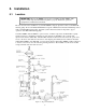
8. Diagrams: Installation / Component DIAGRAM 1. DLC-XP/RC INSTALLATION DRAWING.
DIAGRAM 2. DLC-XP WIRING DIAGRAM (19565-000).
DIAGRAM 3.
9. Specifications Turndown Ratio ......................... up to 10:1 (application dependent) Accuracy .................................... No added inaccuracy to pump flow. Resolution ................................. 0.1%; up to four digits on units of flow. Response ................................... 1% per second Temperature .............................. 18° C to 40° C (0° F to 104° F) Operation 18° C to 60° C (0° F to 140° F) Storage High Voltage Inputs Line Power (J1) .........................
Low Voltage Outputs Analog Output Range / Load...........0 to 20mA / 700ohms Max. Minimum Span .......2mA Fuse.........................50m Surge Protection .....7.4 Joules Isolation ..................500volts from all other I/O and ground Modes .....................Split Ranging / Reverse Acting Alarm Status (J5-3, J5-4) Type........................Dry Contact (Transistor Type) VCE(SAT)..............0.3volts Max Fwd Current ...50mA Maximum voltage...24 VDC On-State Resist .......100 ohm Isolation ..........
10. Factory Default Values CALIBRATION Pump Flow Analog Input Analog Output ANALOG INPUT Failure Mode Operating Mode LEAK DETECTION LEVEL SWITCH POWER FAILURE ALARM RELAY SECURITY Type DECIMAL FORMAT Format Position LANGUAGE UNITS BATCH Batch #n Rate Batch #n Duration Batch #n Type DATE/TIME Date Format Time Format Daylight Savings Day of Week VOLTAGE Operating 1-Point Calibration on PULSAR at Rated Flow and Pressure.
11. Trouble Shooting Guide 11.1 System Diagnostics Your DLC contains extensive diagnostics that allow it to determine the source of common problems. If your DLC is not operating properly, your first course of action should be to review the {DIAGNOSTICS} sub-menu in the {CONFIGURE} menu. To access this menu from the standard operating mode follow this procedure (provided your user interface -- keypad and display -- is functioning)]: 1. Press [MOTOR] repeatedly until the display reads {MOTOR OFF}. 2.
Symptom DIAG 8/11 BATTERY: FAIL DIAG 9/11 CIRCUIT: FAIL *RAM* DIAG 9/11 CIRCUIT: FAIL *EEPROM* DIAG 9/11 CIRCUIT: FAIL *MOTOR* MENU (DIAGNOSTICS – Continued) Probable Cause Possible Solution The DLC clock is backed by a Lithium Battery with a 10 year life. The life expectancy is over. The Random Access Memory (RAM) on the mother board cannot be reliably read and/or written to. Contact Technical Services.
Symptom Motor will not start. Motor will not stop. PULSAR MOTOR (1-Phase) Probable Cause Possible Solution No Power Supplied. Motor/Starter wired incorrectly. Supply power outside of specification. Motor key not pressed. Software did not initiate properly. Leak or Drum input set with option MOTOR OFF? set to YES. PULSAR mechanicals locked. Solid-State relay failed. Motor/Starter wired incorrectly. Software did not init properly. Motor key not pressed. Solid-State relay failed.
ANALOG OUTPUT Possible Solution Symptom Probable Cause No Analog (mA) Signal Present. Not tracking. Output wired incorrectly. Output fuse(s) blown. Output not calibrated properly. Symptom Probable Cause No Output. Output wired incorrectly. External Device not powering output. Check wiring. Replace F2 & F3 w/ 50mA@250VAC. Review 7-General Operation: Calibration. ALARM RELAY OUTPUT Possible Solution Alarm Options not set. Symptom Check wiring. Refer to wiring diagram.
BATCH OPERATION Possible Solution Symptom Probable Cause Activated batch appears to be running through batches rapidly. Batch Activated with Old Start Date. For example, today is 4/26/00, You have a repeating batch programmed to start on 4/24/00). The display will show the 'runthrough' of all batches between start the start day and time and today. Batch duration is set to 0 hours and 0 minutes. Repeating Batch will not start. Symptom Message: {Terminated / Press any key} appears during Calibration.
11.2 Encoder Diagnostics Whenever the DLC is re-calibrated it first performs a Zero Calibration. The first portion of the {CALIBRATING ZERO} routine is an encoder test. The DLC will increase the stroke adjustment 1%, while monitoring the encoder output. It will then reverse direction and drive the mechanism to the 0% position. During the 1% increase, the DLC reads the encoder output and compares it to the expected value.
12. Conversion (Manual To DLC-XP/RC) Your PULSAR can be easily converted from a Manual Stroke Adjustment Mechanism to the DLCXP/RC. The DLC-XP effectively replaces the Manual Cover Assembly. Use the following procedure for conversion: 1. While running the pump motor, adjust the stroke setting to approximately 50%. 2. Disconnect the power supply going to the PULSAR drive motor. 3.
13. System Repairs 13.1 Emergency Manual Pulsar Operation. If your DLC-XP/RC is not functioning, you can operate your PULSAR manually without removing the DLC-XP. Follow this procedure: THE ATMOSPHERE MUST BE MADE SAFE (I.E., NON-HAZARDOUS) PRIOR TO ATTEMPTING THIS PROCEDURE. 1. Disconnect the power to the DLC-XP and DLC-RC at the main. 2. Remove wires to J1 LINE POWER and J3 PUMP MOTOR.
8. Orient the DLC-XP properly at a comfortable height above the pump and align the slot in the DLCXP coupling with the 'flats' on the adjustment shaft. You may have to turn the adjustment shaft. If necessary, only turn the adjustment shaft in the counter clockwise direction. 9. Lower the DLC-XP onto the eccentric. It may be necessary to tip the DLC-XP slightly towards the motor to clear the Motor adapter.
Appendix A – Quick Start Guide This 'Quick Start Guide' is intended to provide the minimum amount of information required to install and commission a PULSAR DLC-XP/RC. It is intended for experienced users only. Novice users should review the entire manual. The notation 'PULSAR IOM' refers to the PULSAR Installation Operation Maintenance Instruction Manual provided with your PULSAR metering pump. Preparing... 1. Review the 'Before You Begin' section and all applicable safety information. 2.
Wiring Connections 1. Install a separate 15Amp breaker at the wiring panel to supply the DLC-XP/RC and pump motor. Use 18 AWG wire size or larger. Attach the supply to the J1 terminal block labeled 'POWER IN.' Make 3 connections: Neutral, Earth (ground) and Hot as labeled. 2. Connect the pump motor to the J3 terminal block labeled 'MOTOR AC/DC.' Use 18 AWG wire size or larger. The pump motor must be wired to operate at the DLC-XP/RC supply voltage (i.e.
NOTES:
Engineered Pump Operations 2 8 8 3 B r i g h t o n - H e n r i e t t a T o wn l i n e R o a d Rochester, NY 14623 Telephone (585) 292-8000 Fax (585) 424-5619 h t t p : / / w w w. p u l s a . c o m pulsa@idexcorp.