
User Instructions


1
AWOP-225SR
v.1.0
Distribution Junction Box 2x2,5mm
2
Edition: 4 from 21.05.2019
Supercedes the edition: 3 from 18.09.2014
1. Description.
The junction box for fire alarm systems is designed for connecting fire protection devices in cable
installation systems with fire resistance according to the DIN 4102-12 standard, where the uninterruptible power
supply or transmission of the signal in case of fire is required.
The junction box is designed to guarantee the mechanical ability to keep the cable routes capable of
guaranteeing the uninterruptible power supply and transmission of telecommunication signals in the fire zone.
The junction box can be used for power supply of fire protection equipment, such as ventilators and smoke
vents, fire alarm control panels, emergency warning systems, etc.
Juction box enable to connect and split 2 wires cable.
The enclosure s equipped with mounting sleeves to mount the optical - acoustic indicator.
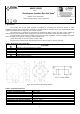
Table 1. Elements of the junction box.
Component
No.
Description
[1]
Mounting holes for mounting to a surface.
[2]
Cable glands.
[3]
Protection connector PE.
[4]
Connection sockets.
[5]
Mounting for indicator
[6]
Cable gland for indicator
Fig.1. The junction box and wiring diagram.
Table 2. Technical parameters.
Voltage
450V AC max
Diameter of installation cable
Max. 10mm
Cross-section of the cable
Max. 2,5mm
2
Protection class
IP20
Enclosure
DC01 1mm steel plate, color RAL 3001 (red)
Dimensions
120 x 120 x 37 [mm] (WxHxD)
Temperature range during installation
-25ºC for +60ºC
Mounting
100mm Φ5,5 mm
Net/gross weight
0,43kg /0,47 kg
EN*