PSU-B-13,8V/L-2A/1/EL-TR-17Ah/MC AWZ 201 v.1.0 Linear, buffer type power supply EN Release: 1 dated 12.10.
TABLE OF CONTENTS: 1. Technical description 2. Installation 3. Handling and operation 4. Maintenance 1. Technical description. The buffer power pack is dedicated for uninterrupted power supply for the equipment requiring the stabilized voltage 12V DC (±15%). The linear stabilizing system applied in the equipment delivers the voltage with lower level of noise and shorter response time for the interference as is the case where a pulse stabilizer is applied.
Technical parameters Power supply voltage Transformer Output voltage Uout 230V AC, 50 Hz (-15%/+10%) TR 50 VA *12.8 V ÷ 13.8 V DC 13.8 V DC – rated 13.4 V DC @ 2A Imax – 2A (const.) 28 W I-st grade - 200% ÷ 250% of supply power – limitation of current and/or fuse failure in the battery circuit (fuseelement replacement required) II – nd.
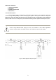
Figure 3. General view of the power pack.
~AC~ joint F1 [2] fuse in transformer circuit [3] Battery outputs Red diode [4] optical signalling Green diode [5] optical signalling Outputs [6] Joint (Tab. 3) P1 [7] Voltage adjustment 230 – 0V [8] Battery joint 230V/AC F2 [9] Transformer primary circuit fuse Joint (with yellow-green [10] PE protective conductor) Tab. 2. Description of designations from the figure 3. [1] [6] +OUT -OUT TAMPER PL + Vcc output - GND output Sabotage prevention contacts – NC Tab. 3. Description of the output joint.
4. Connect the leads of the consumers to joints OUT + and - of the joint box on the power pack board [6]. (Optionally connect the MZN1 module between +OUT- and load). 5. Activate the 230 V AC power supply and insert the power network fuse protecting the transformer primary circuit [9]. Check the optical signalling of the power pack operation. The output voltage of the unloaded power pack is equal to ~ 13.8 V DC. The voltage may fluctuate from 12.8 V to 13.8 V DC during battery charging. 6.
3.3. Procedures in the case of power pack overloading. The power pack is equipped with the protection of the output stage with the application of the PTC polymer fuse. When the power pack is loaded with current exceeding 2A (110%÷150% P), the automatic disconnection of the output voltage takes place which is signalled by the green diode going off. In such a case, the load should be disconnected from the output of the power pack for the period of about 1 minute. 4. Maintenance.
WEEE MARK The waste electric and electronic products do not mix with general household waste. There are separate collection system for used electric and electronic products in accordance with legislation under the WEEE Directive and is effective only with EU. Notice: The power supply unit is adapted for cooperation with the sealed lead-acid battery (SLA). After the operation period it must not be thrown but recycled according to the applicable law. GENERAL WARRANTY CONDITIONS 1. Pulsar K. Bogusz Sp.j.