
User Instructions

2
Table 1. The description of components and connectors of the module.
3. Table 2. Specifications.
No.
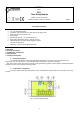
[Fig.1]
Description
Connector:
+12V- - The module’s power supply, DC voltage
S+ - control input supplied by the positive power supply
S- - control input activated by the negative power supply (power supply minus)
R- - Reset input activated by the ground (power supply minus)
- REL relay connector
CAUTION! In Fig.1 the set of contacts shows a potential-free status of the relay.
LED (green): – optical indication
green – supply voltage
green – trigger signal indication (S + or S-)
red – The REL relay activation indication – (the LED is on when the relay is activated)
Potentiometer for T1 trigger time adjustment
Time range jumper T1:
1s – 60s. time range
5s – 5 min. time range
Description: jumper on, jumper on
Potentiometer for T2 relay activation time adjustment
Time range jumper T2:
1s – 60s. time range
5s – 5 min. time range
Description: jumper on, jumper on
Relay
Supply voltage
10÷14V DC
Power consumption
15 mA – inactive relay /35 mA - active relay (±5%)
S+ input
10÷14V DC control
S- input
0V (GND) control
R- input
0V (GND) control
Time range
Time T1: range 1s ÷ 60s and 5s ÷ 5min.
Time T2: range 1s ÷ 60s and 5s ÷ 5min.
The number of relays
1
Maximum connection voltage
50V AC /30V DC
Maximum connection current
1 A
Maximum contact resistance
<100 mOhm
Optical indication of operation
LED light
Operation parameters
II environmental class,
-10°C - 40°C, relative humidity 20%...90% No condensation.
Dimensions
L=70, W=43, H=23 [mm, +/-2]
Mounting
mounting tape or dowel pins x2 (holes3mm)
Connectors
Ф0,51÷2,05 mm (AWG 24-12)
Net/gross weight
0,04 /0,06 [kg]