USER MANUAL EN Edition: 1 from 03.07.2020 Supersedes the edition: _____ Power supplies AWZG2 series Buffer power supply unit Grade 2.
www.pulsar.
www.pulsar.pl Seria AWZG2 In case of power failure, a battery back-up is activated immediately.. The PSU is housed in a metal enclosure (colour RAL 9003) which can accommodate a battery. A micro switch indicates door opening (front cover).
www.pulsar.pl Seria AWZG2 1.3. Description of components and connectors. Table 1. Elements of the PSU pcb (see: tab. 2a,b,c). Element no. Description START button (launching from battery) VADJ potentiometer, adjustable output voltage FBAT fuse in the battery circuit Terminals: ~AC~ – AC power input EPS – technical output of AC power loss indication hi-Z state = AC power failure 0V state = AC power - O.K. APS – technical output of battery failure hi-Z state = failure 0V state = PSU status O.K.
www.pulsar.pl Seria AWZG2 . Fig. 2b. View of PCB board of 12V3A / 24V2A model Fig. 2c. View of PCB board of 12V5A / 24V3A model Table 2. Elements of PSU (see: tab. 3). Element no. Description Isolation transformer Pcb of the PSU (Tab. 1, Fig.
www.pulsar.pl Seria AWZG2 Fig.3. View of PSU. 1.4. Specifications: - electrical specifications (tab.3) - mechanical specifications (tab.4) - operation safety (tab.5) - operating specifications (tab. 6) Table 3. Electrical parameters. Models PSU type Supply voltage Current consumption Power frequency PSU power Output current (max.) Efficiency Output voltage Voltage adjustment range Ripple voltage (max.
www.pulsar.pl Seria AWZG2 Battery circuit protection SCP and reverse polarity connection - FBAT fuse (in case of a failure, fuse-element replacement required) U<20 V (± 0,5V) – disconnection of battery terminal - LEDs on PCB of power supply unit - LED indicators on power supply’s cover (see section 3.1) Deep discharge battery protection UVP Optical indication U<10 V (± 0,5V) – disconnection of battery terminal Technical outputs: - OC type: 50mA max.
www.pulsar.pl Seria AWZG2 Vibrations during operation Impulse waves during operation Direct insulation Vibrations and impulse waves during transport unacceptable unacceptable unacceptable Wg PN-83/T-42106 2. Installation. 2.1. Requirements. The buffer PSU is to be mounted by a qualified installer, holding relevant permits and licenses (applicable and required for a given country) for 230 V interference and low-voltage installations.
www.pulsar.pl Seria AWZG2 7. Switch on the 230 V supply. The green AUX and yellow LB LEDs on the power supply PCB should be ON while charging the battery. Output voltage of the PSU, without load U = 13,8 V DC (or 27,6 V DC). During battery charge, voltage can amount to U = 11 - 13,8 V DC (or 22 - 27,6 V DC). 8. Run the PSU test: check the LED (Tab. 7), technical output; through:: - cutting off the 230 V current: LED AC (Fig.
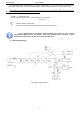
www.pulsar.pl Seria AWZG2 Fig. 4. Electrical diagram of OC outputs. 3.3. Technical outputs – relay. If the OC type outputs are not sufficient to control the unit, it is possible to use the AWZ639relay module changing technical outputs of the OC type to relay type. Fig. 5. The diagram of connecting the AWZ639 module. 3.4. Standby time. Battery-assisted operating depends on battery capacity, charging level and load current.
www.pulsar.pl Seria AWZG2 3.6. Running PSU on battery backup. Power supply allows you to run on battery backup when necessary. To do this, press the START button on PCB. 4. Operation and use. 4.1. Overload or short circuit of the PSU output (SCP on). The AUX output is equipped with an electronic protection. If power supply is loaded with current exceeding IMAX. (load 110% ÷ 150% of PSU power), current and voltage are automatically limited.