
User Instructions


4
2.2. Installation procedure.
1. Mount the enclosure (cabinet, etc.) and lead cables through cable glands.
2. Mount the DC/DC converter with adhesive tape or mounting screws.
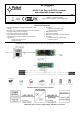
3. Supply DC voltage to the + IN, -IN terminals with correct polarization.
4. Switch on the DC voltage.
5. Use the jumper to set the required voltage range and adjust the required output voltage with the V
ADJ
potentiometer. Default setting:
24V.
6. Switch off the DC voltage.
7. Connect the receivers’ cables to the +AUX, -AUX connectors of the terminal block on the module’s board.
8. Connect the device cables (alarm control panel, indicator, LED light, etc.) to the PSU technical output if necessary.
9. Switch on the DC voltage (the red IN LED should be permanently illuminated, the AUX green LED should be permanently
illuminated).
10. Once the tests and operation control are performed, close the enclosure, cabinet, etc.
3. Converter 's module operation indication.
3.1. Technical output.
The converter is equipped with three diodes indicating operation status: IN, AUX, and PSU.
IN- red LED: during normal status (DC power supply) it is lit continuously. No DC supply is indicated by switching off the IN LED.
AUX- green LED: indicates DC supply status at the module’s output. During normal status, it is lit continuously, in case of short
circuit or overload the AUX led is off.
PSU- red LED: indicates module’s overload. During normal status, it is off, in case of short circuit or overload the LED lights
continuously.
3.2. Technical output.
The converter is fitted with one technical output indicating failure of the DC / DC module.
PSU- OLP/SCP (overload/short-circuit) output: - OC type output indicating overload/short-circuit of the module’s output.
During normal operation, the output is shorted to the AUX - (0V). In case of failure, the module disconnects the output and it is in the hi-
Z (high impedance) state during failure.
4. Maintenance and operation.
4.1. Converter overload.
The AUX output is protected with the PTC polymer fuse. If the load current exceeds Imax (110% ÷ 150% @ 25ºC of the
converter capacity), the output voltage will be automatically disconnected, which will be signaled by switching off the green AUX LED,
switching on the red PSU LED and a change in the status of the technical output. Voltage restoration requires disconnecting the output
load for approx. 1 min.
5. Maintenance.
All maintenance procedures can be performed after disconnecting the converter from the power network. The converter does
not require any specific maintenance; however, its interior should be cleaned with compressed air if used in dusty conditions.
WEEE LABEL
Waste electrical and electronic equipment must not be disposed of with normal household waste.
According to the European Union WEEE Directive, waste electrical and electronic equipment should be
disposed of separately from normal household waste.
Pulsar sp. j.
Siedlec 150, 32-744 Łapczyca, Poland
Tel. (+48) 14-610-19-40, Fax. (+48) 14-610-19-50
e-mail: biuro@pulsar.pl, sales@pulsar.pl
http:// www.pulsar.pl, www.zasilacze.pl