
User Instructions

3
1.3. Technical parameters:
- Electrical parameters (Table 3)
- Mechanical parameters (Table 4)
Table 3.
The input voltage range (power supply)
9,5V÷16V DC
The output voltage range
5V÷15V, factory setting: 12V
P module power
36W max. (see fig.3)
Energy efficiency
82%÷ 88%
Ripple voltage
60mV p-p max
Output current
3,0A max. (See fig.3)
Current consumption by module systems
15 mA max.
Short-circuit protection SCP
electronic, automatic recovery
Overload protection OLP
110-150% of the module’s power, manual restart (the failure
requires disconnection of the DC output circuit)
Technical outputs
- PSU output indicating failure – overload or short-
circuit in the AUX output
- OC type, 50mA max. Failure status: hi-Z state (high
impedance), normal status: L level (0V)
Optical indication
- IN LED indicating DC power status
- AUX LED indicating DC supply status at the output
- PSU LED indicating failure - overload or short-
circuit in the AUX output
- red, normal status: is lit continuously
- green, normal status: is lit continuously
- red, normal status: does not lit, failure: is lit continuously
Operating conditions
II environmental class, -10°C ÷40°C, ensure air flow around
the unit for convection cooling
Declarations, Warranties
CE, 2 years from the production date
Table 4.
Dimensions
L=140, W=43, H=45 [+/- 2mm]
Mounting
tape or mounting screw x 2
Terminals
Ф0,41÷1,63 (AWG 26-14)
Net/gross weight
0,13/0,17 kg
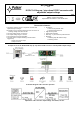
2. Installation.
2.1. Requirements.
The DC/DC converter is to be mounted by a qualified installer, holding relevant permits and licenses (applicable and required
for a given country) for step down installations. The module should be mounted in confined spaces with normal relative humidity
(RH=90% maximum, no condensation) and temperature range from -10°C up to +40°C. The module should operate in vertical position
in order to provide free and convectional air flow.
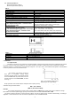
Proper operation of the module requires adequate current capacity of the power source; the power supply capacity should be
calculated using the formula below:
PIN = 1,25 x PAUX
(PIN = 1,25 x IAUX x UAUX)
Example:
The converter will supply the receivers with a capacity of P
AUX
= 36W drawing a total current of I
AUX
= 3A at the voltage
U
AUX
= 12V. The minimum power supply capacity must therefore amount to: P
IN
= 1,25 x 3A x 12V = 45W.
The device should be mounted in a metal enclosure (cabinet). The rules for power supply, enclosures and shielding - according to
application - must be observed in order to meet the requirements of LVD and EMC directives.
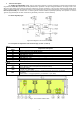
The module's load balance should be
done prior to installation. During normal
operation, the total current of the receivers should
not exceed I=3A while the power drawn from the
module should not exceed Pmax=36W, as shown
in the Fig. 3.
Fig.3. The maximum output current
depending on the output voltage.