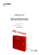
EN54-2A17LCD v.1.0 EN54 27,6V/2A/2x17Ah/LCD power supply for fire alarm systems EN** Edition: 1 from 28.11.
www.pulsar.pl EN54-2A17LCD RED POWER TABLE OF CONTENTS 1. PSU FEATURES: ...............................................................................................................................4 2. PACKAGE CONTENTS....................................................................................................................5 3. FUNCTIONAL REQUIREMENTS OF THE PSU. ..........................................................................6 4. TECHNICAL DESCRIPTION. ..............................
www.pulsar.pl EN54-2A17LCD RED POWER 8. RESERVE POWER SUPPLY CIRCUIT........................................................................................38 8.1. BATTERY DETECTION.................................................................................................................................................. 38 8.2. PROTECTION AGAINST SHORT -CIRCUIT OF THE BATTERY TERMINALS............................................................................ 38 8.3.
www.pulsar.pl EN54-2A17LCD RED POWER 1.
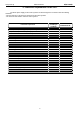
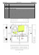
www.pulsar.pl EN54-2A17LCD 2. Package contents.
www.pulsar.pl RED POWER EN54-2A17LCD 3. Functional requirements of the PSU. The buffer power supply for fire alarm systems has been designed in accordance with the following standards: - EN 54-4:2001 and / A2:2007 Fire detection and fire alarm systems. - EN 12101-10:2007 Smoke and heat control systems.
www.pulsar.pl EN54-2A17LCD RED POWER 4. Technical description. 4.1. General description. The buffer power supply has been designed for an uninterrupted supply of fire alarm systems, smoke and heat control systems, fire protection equipment and fire automatics requiring stabilized voltage of 24V DC (± 15%). The PSU is fitted with two independently protected outputs AUX1 and AUX2, which supply voltage of 27.
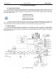
www.pulsar.pl RED POWER EN54-2A17LCD 4.3. Description of components and power supply terminals. Table 1. Components of the Power supply PCB (Fig. 2). Co mpo nent No.
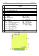
www.pulsar.pl RED POWER EN54-2A17LCD Table 2. Components of the PCB of the EMC filter (Fig. 3). Element Description No. FMAINS fuse in the power supply circuit 230V, T1A / 250V L-N power supply connector 230V AC, Connector– for connecting the PSU. PE protective connector Fig. 3. The view of the EMC filter.
www.pulsar.pl EN54-2A17LCD Table 3. Elements of the PSU (see Fig. 4). Component Description No. [1] Isolation transformer [2] Printed Circuit Board (see Table 1, Fig. 2) [3] Battery temperature sensor. Space to install an additional module: [4] “INTR”, “INTE”, “INTW”, [5] Place to install the EN54-LB4 or EN54-LB8 fuse module [6] TAMPER; microswitch (contacts) of antisabotage protection (NC) [7] EMC filter module (see Table 2, Fig.
www.pulsar.pl EN54-2A17LCD RED POWER 5. Installation. 5.1. Requirements. The PSU is to be mounted by a qualified installer, holding relevant permits and licenses (applicable and required for a given country) for 230V/AC in and low-voltage installations. As the power supply is designed for a continuous operation and is not equipped with a powerswitch, therefore, an appropriate overload protection in the power supply circuit should be provided.
www.pulsar.pl RED POWER EN54-2A17LCD 1. Mount the PSU in a selected location with use of special metal expansion bolts. Do not use PVC dowels. 2. Connect the power cables (230V AC) to L-N terminals of the PSU. Connect the ground wire to the terminal marked with grounding symbol: PE. Use a three-core cable (with a yellow and green PE protection wire) to make the connection.
www.pulsar.pl EN54-2A17LCD RED POWER 6. FUNCTIONS. 6.1. Control Panel. The PSU features a panel with buttons and LCD display, enabling reading of all the available electrical parameters. The panel buttons are used to select and confirm the parameters, which should be displayed Fig. 7. Control panel. Table 6. The description of the buttons and LEDs of the LCD panel.
www.pulsar.pl RED POWER EN54-2A17LCD 6.2. First run of the PSU – language selection screen. During the first run of the PSU, language selection screen will be displayed. Use the „<” or „>” buttons to select the available languages. After selecting the appropriate language, confirm by pressing the "SET" button. The main screen will be displayed. Fig. 8. Language selection screen. If the language selection is not done, language selection screen will be displayed on the next startup.
www.pulsar.pl EN54-2A17LCD RED POWER 6.4. Information displayed on the LCD panel. 6.4.1. Preview menu. Pressing the „ESC” button at the bottom of the display starts the preview menu, allowing to choose one of the four available PSU screens. Use the „<” or „>” buttons to choose a proper screen and press the „SET” button to confirm. - current parameters of the PSU (see section 6.4.2) - current failures of the PSU (see section 6.4.3) - parameters of the PSU stored in the memory (see section 6.4.
www.pulsar.pl RED POWER EN54-2A17LCD 6.4.2. LCD screen – current parameters . icon and press the To set the screen, press the „ESC” button, use the „<” or „>” buttons to choose the „SET” button to confirm. The screen displays electrical parameters and the status of the technical outputs during operation. Illumination of an element informs about an activation and reflects the status of LEDs on the PCB of the PSU (see Table 1, [10]). Fig 10. LCD panel – PSU parameters. Table 8.
www.pulsar.pl RED POWER EN54-2A17LCD . 6.4.3. LCD screen – current failures In case of abnormal electrical parameters during the operation, the PSU will indicate a failure by displaying a message on the LCD, turning on the red LED ALARM on the panel, activating acoustic indication (if enabled) and changing the status of a dedicated technical output. Fig. 11. Message indicating blown fuse at the AUX2 output. At a given time, multiple failures can occur.
www.pulsar.pl EN54-2A17LCD RED POWER Fig. 14. Screen of the history of PSU’s parameters. In order to change the displayed parameter, highlight its name by pressing the „SET” button and use the „<” or „>” buttons to choose the requested parameter. Pressing the „SET” button again will highlight the time range of the chart, which also can be changed with the „<” or „>” buttons.
www.pulsar.pl EN54-2A17LCD 6.4.5. LCD screen – history of events RED POWER . In case of abnormal electrical parameters during the operation, the PSU will indicate a failure by displaying a message on the LCD, periodically turning on and off the LCD backlight, turning on the red LED ALARM on the panel, activating acoustic indication (if enabled) and changing the status of a dedicated technical outputs.
www.pulsar.pl RED POWER EN54-2A17LCD 6.4.6. List of failure codes and information messages. The PSU indicates the operation status with the appropriate code. The codes are divided into two groups, marked with the initial letters "F" or "I”. The codes beginning with the letter "F" indicate a failure. The codes that begin with the letter "I" indicate the correct operation of the PSU or repaired fault, involving, for example, fuse replacement: "I03 - BAT fuse replaced”. Table 9. List of PSU failure codes.
www.pulsar.pl EN54-2A17LCD RED POWER Table 10. List of PSU message codes. Message Description code I00 Running the PSU I01 AC power restored AUX1 fuse replaced I02 AUX2 fuse replaced I03 BAT fuse replaced I04 Battery connected I05 Battery OK I06 Correct battery temperature I07 Correct AC voltage I08 EXTo output on I09 EXTo output off I10 Battery test – START I11 PSU’s lid closed I12 The Imax_a current exceeded I13 The current has dropped below Imax_a 6.5. Technical outputs.
www.pulsar.pl EN54-2A17LCD RED POWER The technical outputs have been made with galvanic isolation between the PSU’s systems and the attached devices. Fig. 17. Electrical diagram of technical outputs. 6.6. Input of collective failure EXTi. The EXT IN (external input) technical input indicating collective failure is intended for additional, external devices that generate the failure signal.
www.pulsar.pl EN54-2A17LCD RED POWER 6.7. Indication of the enclosure opening - TAMPER. The PSU is fitted with the microswitch tamper indicating enclosure opening. The tamper cable is not connected to the terminal in the factory settings. In order to activate tamper, remove the jumper from tamper terminal (Fig. 2 [12]) and plug in the tamper cable.
www.pulsar.pl EN54-2A17LCD RED POWER 6.9. Overvoltage protection of the PSU output OVP. In case of voltage exceeding 30,5V±0.5V at the switching regulator’s output, the system cuts off the power at the outputs to protect the battery and the receivers from damage. The outputs will be batterypowered. The activation of the protection system is indicated by the OVP red LED on the PCB board, and the PSU FLT and ALARM outputs. 6.10. PSU overload.
www.pulsar.pl RED POWER EN54-2A17LCD 7. PSU settings. The PSU has a configuration menu, allowing to configure the PSU settings by changing or activating certain parameters. To enter the setting mode, press the "SET" button from the main screen’s level. Fig. 22. PSU settings screen. 7.1. Password. The PSU supports two levels of access to configuration, which limit the possibility of changing the PSU’s settings from the LCD panel. Both levels are protected by a separate password.
www.pulsar.
www.pulsar.pl EN54-2A17LCD RED POWER 7.1.5. Keyboard lock. When entering passwords, it is possible to choose whether the buttons on the front panel of the PSU's should be locked. It is enabled by „Keyboard password” option.
www.pulsar.pl RED POWER EN54-2A17LCD 7.2. PSU. The “PSU” menu is only available after entering the correct service password. Selecting the “PSU” in the settings menu will display another menu, allowing full configuration of the PSU; battery test ON/OFF, acoustic indication ON/OFF, EXTo output ON/OFF, setting the delay time for EPS output, setting the communication parameters.
www.pulsar.pl RED POWER EN54-2A17LCD - When performing the test, the LCD will display the ”WAIT” message. 7.2.2. Acoustic indication ON/OFF Emergency situations that may arise during the operation of the PSU are indicated acoustically. The frequency and number of signals depend on the type of event (see section 6.4.6.). Table 13. Acoustic indication. No.
www.pulsar.pl EN54-2A17LCD RED POWER 7.2.3. EXTo output ON/OFF Controlled relay output EXTo (external output) does not depend on the operation of the power supply unit and can be switched independently of its work. The EXTo output can be used for switching between controlling, resetting and supplying inputs/outputs in low-voltage electrical circuits. Changes in the EXTo output can be made locally from the panel (section 7.2.3.) or remotely using the PowerSecurity application.
www.pulsar.pl EN54-2A17LCD RED POWER - press the „SET” button, the prompt will appear at the end of the line - use the „<” or „>” buttons to set the delay time: - 10s - 1min - 10min - 30min - confirm by pressing the „SET” button 7.2.5. Setting the communication address applies to cooperation with PowerSecurity. All power supplies are factory-set to address 1.
www.pulsar.pl EN54-2A17LCD 7.2.6. Setting the transmission parameters RED POWER applies to cooperation with PowerSecurity. All the parameters responsible for communication between the PSU and the computer, namely the address, parity and speed should have the same settings for both the PSU and the PowerSecurity program. The PSU has preset transmission parameters of 115200 baud 8E1; if these values were changed, they should be restored to original settings.
www.pulsar.pl EN54-2A17LCD RED POWER 7.3. Control panel. The menu is only available after entering the correct user’s or service password. The „control panel” menu enables configuration of the settings directly related to the user interface. It is possible to set the display language, date, time, intensity of the backlight and blinking light indicating failure. Setting the correct date and time is important for keeping chronology of events stored in the internal memory.
www.pulsar.pl EN54-2A17LCD RED POWER 7.3.1. Setting the display language One of the functions of the control panel menu is the possibility to select language. Display language can be set according to personal preference. - use the „<” or „>” buttons to display the Language menu - press the „SET” button, the prompt will appear at the end of the line - use the „<” or „>” buttons to choose the display language - confirm by pressing the „SET” button 7.3.2.
www.pulsar.pl EN54-2A17LCD RED POWER 7.3.3. Setting the time The „Time” menu in the „Control panel” menu enables setting the correct time, according to which error messages and operation history will be saved. Built-in real time clock does not take into account leap year and the changes resulting from the switch between summer and winter time. These changes should be taken into account when analyzing events recorded in the history.
www.pulsar.pl EN54-2A17LCD RED POWER - press the „SET” button, the prompt will appear at the end of the line - use the „<” or „>” buttons to set the required brightness - confirm by pressing the „SET” button 7.3.5. Contrast setting The „Contrast” menu in the „Control panel” enables setting the contrast of the display text.
www.pulsar.
www.pulsar.pl EN54-2A17LCD RED POWER 8. Reserve power supply circuit. The PSU is fitted with intelligent circuits: battery charging circuit with the function of the accelerated charging and battery control, which main task is to monitor the condition of the batteries and the connections in the circuit. If the controller detects a power failure in the battery circuit, appropriate indication and activation of the APS FLT and ALARM technical outputs takes place. 8.1. Battery detection.
www.pulsar.pl EN54-2A17LCD RED POWER The battery test will also be automatically locked when the PSU is in the operating mode, in which the battery test is impossible. Such condition occurs, for example, during battery assisted operation or when the power supply is overloaded. In this case, the LCD will display the crossed out „START” message in the PSU Settings -> PSU -> Battery test menu. Fig. 28. Battery test – inactive. 8.6. Measurement of the resistance of the battery circuit.
www.pulsar.pl EN54-2A17LCD RED POWER 9. Remote monitoring (options: Wi-Fi, Ethernet, RS485, USB). The PSU has been adjusted to operate in a system that requires a remote control of the parameters in a monitoring centre. Transmitting data concerning PSU status is possible due to an additional, external communication module responsible for communication in Wi-Fi, Ethernet or RS485 standard. It is possible to connect the PSU and the computer via the USB –TTL interface.
www.pulsar.pl EN54-2A17LCD RED POWER The RS485-ETHERNET „INTRE” interface is a device used to convert signals between the RS485 bus and the Ethernet network. For proper operation, the unit requires an external power supply in the range of 10÷30V DC e.g. drawn from a PSU of the EN54 series. The physical connection of the interface takes place under galvanic isolation. The unit is mounted in a hermetic enclosure protecting against adverse environmental conditions. Fig. 31.
www.pulsar.pl EN54-2A17LCD RED POWER The RS485-WiFi „INTRW” interface is a device used to convert signals between the RS485 bus and the WiFi network. For proper operation, the unit requires an external power supply in the range of 10÷30V DC e.g. drawn from a PSU of the EN54 series. The physical connection of the interface takes place under galvanic isolation. The unit is mounted in a hermetic enclosure protecting against adverse environmental conditions. Fig. 33.
www.pulsar.pl EN54-2A17LCD RED POWER 9.5. „PowerSecurity” program. The ”Power Security” program is available on www.pulsar.pl Its detailed description can be found in the manual. „Power Security” is a free computer program developed to view and analyze the information sent from the PSU installation spots. The main panel is presented below. Fig. 35. “Power security” main panel. It is possible to divide the main panel of the program into smaller areas, depending on the number of monitored power supplies.
www.pulsar.pl EN54-2A17LCD RED POWER 10. Technical parameters. Electrical parameters (Table 15). Mechanical parameters (Table 16). Safety of use (Table 17). Operation parameters (Table 18) Table 15. Electrical parameters.
www.pulsar.
www.pulsar.pl EN54-2A17LCD RED POWER 11. Technical inspections and maintenance. Technical inspections and maintenance can be performed after disconnecting the power supply from the power network. The PSU does not require any specific maintenance, however, its interior should be cleaned with compressed air if it is used in dusty conditions. In case of fuse replacement, use only compatible replacement parts. Technical inspections should be carried out not less frequently than once per year.
www.pulsar.pl EN54-2A17LCD RED POWER WEEE MARK According to the EU WEE Directive – It is required not to dispose of electric or electronic waste as unsorted municipal waste and to collect such WEEE separately. CAUTION! The power supply unit is adapted for cooperation with the sealed lead-acid batteries (SLA). After the operation period they must not be thrown but recycled according to the applicable law . GENERAL WARRANTY CONDITIONS 1. Pulsar K. Bogusz Sp.j.
www.pulsar.pl EN54-2A17LCD Pulsar K.Bogusz Sp.j. Siedlec 150, 32-744 Łapczyca, Polska Tel. (+48) 14-610-19-40, Fax. (+48) 14-610-19-50 e-mail: biuro@pulsar.pl, sales@pulsar.pl http:// www.pulsar.pl, www.zasilacze.