
Operating instructions

www.pulsar.pl EN54-2A17LCD RED POWER
10
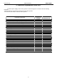
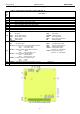
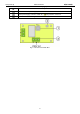
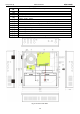
Table 3. Elements of the PSU (see Fig. 4).
Component
No.
Description
[1]
Isolation transformer
[2]
Printed Circuit Board (see Table 1, Fig. 2)
[3]
Battery temperature sensor.
[4]
Space to install an additional module:
“INTR”, “INTE”, “INTW”,
[5]
Place to install the EN54-LB4 or EN54-LB8 fuse module
[6] TAMPER; microswitch (contacts) of antisabotage protection (NC)
[7]
EMC filter module (see Table 2, Fig. 3)
[8]
2x17Ah batteries
[9]
Embossing for cable gland
[10]
Embossing for cable gland (WiFi antenna or cable communication interface)
[11]
Embossings for concealed wires
[12]
Lock
[13]
Battery connectors; positive: +BAT = red, negative: - BAT = black
Fig.4. The view of the PSU.