
Operating instructions

www.pulsar.pl EN54-2A17LCD RED POWER
12
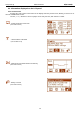
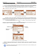
1. Mount the PSU in a selected location with use of special metal expansion bolts. Do not use PVC dowels.
2. Connect the power cables (230V AC) to L-N terminals of the PSU. Connect the ground wire to the terminal
marked with grounding symbol: PE. Use a three-core cable (with a yellow and green PE protection wire) to
make the connection.
The shock protection circuit shall be done with a particular care: the yellow and green wire coat of
the power cable should be connected to the terminal marked with the PE symbol on the PSU
enclosure. Operation of the PSU without the properly made and fully operational shock protection circuit
is UNACCEPTABLE! It can cause damage to the equipment or an electric shock.
3. Connect the receivers’ cables to the AUX1 and AUX2 output terminals on the PSU board.
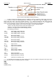
4. If needed, connect the cables from the devices to the technical inputs and outputs:
- ALARM; technical output of collective failure of the PSU
- EPS FLT; technical output of AC power loss indication
- PSU FLT; technical output of PSU failure.
- APS FLT; technical output of the battery failure.
- EXTi; input of collective failure
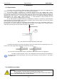
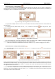
5. Install the batteries in a designated area of the enclosure (see Fig. 4). Connect the batteries with the PSU
paying special attention to the correct polarity. Batteries must be connected in series using the special
cable (included).
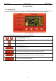
6. Switch on the 230V AC supply. The corresponding LEDs on the power supply PCB should be ON: red AC
and green AUX1 and AUX2. Yellow LB LED should light up while charging.
7. Check the current consumption of the receivers, taking into account the battery charging current, so as not
to exceed the total current efficiency of the PSU (see section 4.1).
8. Once the tests are completed, close the enclosure.
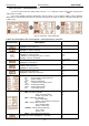
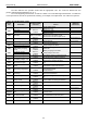
Table 4. Operation parameters.
Environmental class PN-EN 12101-10:2007 1
Operating temperature -25ºC...+55ºC ; 75 ºC for 2 hours
Storing temperature -25ºC...+60ºC
Relative humidity 20%...90%, no condensation
Sinusoidal vibrations during operation:
10 ÷ 50Hz
50 ÷ 150Hz
0,1g
0,5g
Surges during operation 0,5J
Direct insolation unacceptable
Vibrations and surges during transport According to the PN-83/T-42106 standard
Table 5. Factory settings of the PSU.
Delay time for EPS technical output
indicating AC power loss
10s See section 7.2.4.
Acoustic indication ON See section 7.2.2.
EXTo output OFF See section 7.2.3.
Communication address 1 See section 7.2.5.
Transmission 115.2k 8E1 See section 7.2.6.
Backlight Constant – 50% See section 7.3.4.
Blinking light indicating failure ON See section 7.3.4
Passwords:
- user password
- service password
- keyboard lock
1111
1234
NO
See section 7.1