Modbus Protocol for EN54 Power Supplies Edition: 2 from 15-01-2018 Supersedes the edition: 1 from 30-08-2017 Strona 1 z 6
Contents 1. Revision history ............................................................................................................................... 3 2. The Modbus Protocol ...................................................................................................................... 3 3. Function codes ................................................................................................................................ 3 4. Read Input Registers..............................
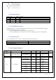
1. Revision history Version 1.0 1.1 Date 1.06.2017 15.01.2017 Author BTR BTR Changes Initial release Added Write Multiple Registers 2. The Modbus Protocol The Modbus Protocol is an industrial communication protocol that is currently used in EN54 Power Supplies. The Power Supplies use two type of connections: RS-485 - Modbus RTU (115200 kbps, 8E1 – default settings) TCP/IP - Modbus RTU over TCP (See the instruction of the appropirate interface: INTE, INTW) 3.
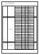
04 05 Error flags (2) Led, beeper, tamper state F15 - -High battery temperature 9 1-bit F21 - Cover opened 10 1-bit F52 - Internal supply fail 11 1-bit F19 - High AC voltage 12 1-bit F20 - Low AC voltage 13 1-bit F60 - No communication 14 1-bit F61 - Control panel fail 15 1-bit F05 - Battery test error 0 1-bit F03 - Battery fuse fail 1 1-bit F02 - AUX1 fuse fail 2 1-bit F04 - Output overload 3 1-bit 4 1-bit 5 1-bit 6 1-bit 7 1-bit 8 1-bit 9 1-bit 10 1-bit 1
06 09-17 29 30 Signals state Measurements Buzzer and EXTo settings EPS time settings 1 – on 0 – off 1 – on 0 – off 1 – on 0 – off 1 – on 0 – off 1 – on 0 – off 1 – on 0 – off 1 – on Buzzer 5 1-bit Led EXTo 6 1-bit Led EXTi 7 1-bit Led ALARM 8 1-bit Led APS 9 1-bit Tamper 13 1-bit Battery charging 0 1-bit Battery test in progress 2 1-bit Start of power supply 4 1-bit 5 1-bit 6 1-bit Technical output APS 8 1-bit Technical output PSU 9 1-bit Technical output EPS 1
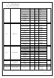
5. Write Multiple Registers Register address Register description Function description Position Type Buzzer 3 1-bit EXTo 4 1-bit Dims the display after 5 minutes 5 1-bit Buzzer, EXTo, Display settings 128 Format Access 0 – off 1 – on 0 – off 1 – on 0 – off 1 – on W Attention: Jumper Z2 must be inserted in the socket on the pcb. 6.