
Modbus Protocol


Strona 5 z 6
1 – on
Buzzer
5
1-bit
0 – off
1 – on
Led EXTo
6
1-bit
0 – off
1 – on
Led EXTi
7
1-bit
0 – off
1 – on
Led ALARM
8
1-bit
0 – off
1 – on
Led APS
9
1-bit
0 – off
1 – on
Tamper
13
1-bit
0 – off
1 – on
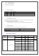
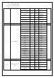
06
Signals state
Battery charging
0
1-bit
0 – inactive
1 – active
R
Battery test in progress
2
1-bit
0 – inactive
1 – active
Start of power supply
4
1-bit
0 – inactive
1 – active
Battery test manually
trigged
5
1-bit
0 – inactive
1 – active
Battery test is
prohibited
6
1-bit
0 – inactive
1 – active
Technical output APS
8
1-bit
0 – inactive
1 – active
Technical output PSU
9
1-bit
0 – inactive
1 – active
Technical output EPS
10
1-bit
0 – inactive
1 – active
Technical output EXTo
11
1-bit
0 – inactive
1 – active
Technical output
ALARM
12
1-bit
0 – inactive
1 – active
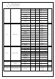
09-17
Measurements
09 - Battery voltage
15…0
uint16_t
0,01 V
R
10 - AUX1 voltage
15…0
uint16_t
0,01 V
11 - AUX1, AUX2
current
15…0
uint16_t
0,01 A
12 - AUX2 voltage
15…0
uint16_t
0,01 V
13 - Output voltage
15…0
uint16_t
0,01 V
14 - Output current
15…0
uint16_t
0,01 A
15 - Battery
temperature
15…0
uint16_t
1 ºC
16 -Battery circuit
resistance
15…0
uint16_t
0,01 Ω
17 - AC voltage
15…0
uint16_t
0,1 V
29
Buzzer and EXTo
settings
Buzzer
2
1-bit
0 – off
1 – on
R
EXTo
3
1-bit
0 – off
1 – on
30
EPS time settings
EPS time
15…0
uint16_t
0 – 10 seconds
1 – 1 minute
2 – 10 minute
3 – 30 minute
R