EN54-3A28 v.1.0 EN54 27,6V/3A/2x28Ah power supply for fire alarm systems EN** Edition: 1 from 28.11.
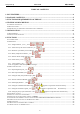
www.pulsar.pl RED POWER EN54-3A28 TABLE OF CONTENTS 1. PSU FEATURES: ...............................................................................................................................4 2. PACKAGE CONTENTS....................................................................................................................5 3. FUNCTIONAL REQUIREMENTS OF THE PSU. ..........................................................................6 4. TECHNICAL DESCRIPTION. .................................
www.pulsar.pl EN54-3A28 RED POWER 7. RESERVE POWER SUPPLY CIRCUIT........................................................................................30 7.1. BATTERY DETECTION. ................................................................................................................................................. 30 7.2. PROTECTION AGAINST SHORT-CIRCUIT OF THE BATTERY TERMINALS............................................................................. 30 7.3.
www.pulsar.pl RED POWER EN54-3A28 1.
www.pulsar.pl EN54-3A28 2. Package contents.
www.pulsar.pl RED POWER EN54-3A28 3. Functional requirements of the PSU. The buffer power supply for fire alarm systems has been designed in accordance with the following standards: - EN 54-4:2001 and / A2:2007 Fire detection and fire alarm systems. - EN 12101-10:2007 Smoke and heat control systems.
www.pulsar.pl EN54-3A28 RED POWER 4. Technical description. 4.1. General description. The buffer power supply has been designed for an uninterrupted supply of fire alarm systems, smoke and heat control systems, fire protection equipment and fire automatics requiring stabilized voltage of 24V DC (± 15%). The PSU is fitted with two independently protected outputs AUX1 and AUX2, which supply voltage of 27.
www.pulsar.pl RED POWER EN54-3A28 4.3. Description of components and power supply terminals. Table 1. Components of the Power supply PCB (Printed Circuit Board) (Fig. 2). Component No.
www.pulsar.pl RED POWER EN54-3A28 Table 2. Components of the PCB of the EMC filter (Fig. 3). Element nr Opis FMAINS fuse in the power supply circuit 230V, T3,15A / 250V L-N power supply connector 230V AC, PE protective connector Connector– for connecting the PSU. Fig. 3. The view of the EMC filter.
www.pulsar.pl EN54-3A28 Table 3. Elements of the PSU (Fig. 4). Component Description No. [1] Isolation transformer [2] Printed Circuit Board (see Table 1, Fig. 2) [3] Battery temperature sensor. Space to install an additional module: [4] “INTR”, “INTE”, “INTW” [5] Place to install the EN54-LB4 or EN54-LB8 fuse module [6] TAMPER; microswitch (contacts) of antisabotage protection (NC) [7] EMC filter module (see Table 2, Fig.
www.pulsar.pl EN54-3A28 RED POWER 5. Installation. 5.1. Requirements. The PSU is to be mounted by a qualified installer, holding relevant permits and licenses (applicable and required for a given country) for 230V/AC in and low-voltage installations. As the power supply is designed for a continuous operation and is not equipped with a powerswitch, therefore, an appropriate overload protection in the power supply circuit should be provided.
www.pulsar.pl RED POWER EN54-3A28 5.2. Installation procedure. CAUTION! Before installation, cut off the voltage in the 230V power-supply circuit. To switch power off, use an external switch, in which the distance between the contacts of all poles in the disconnection state is not less than 3mm 1. Mount the PSU in a selected location with use of special metal expansion bolts. Do not use PVC dowels. 2. Connect the power cables (230V AC) to the L-N terminals of the PSU.
www.pulsar.pl EN54-3A28 RED POWER 6. Functions. 6.1. Control Panel. The PSU features a panel with buttons and LED display, enabling reading of all the available electrical parameters. The panel buttons are used to select and confirm the parameters, which should be displayed. Fig. 7. Control panel. Table 6. The description of the buttons and LEDs of the LED panel.
www.pulsar.pl RED POWER EN54-3A28 6.2. Main menu. The PSU is equipped with a menu, which allows to preview the current electrical parameters. Diagram explaining the menu structure is presented below Fig. 8. Menu of the display. Table 7. The description of display symbols.
www.pulsar.pl EN54-3A28 RED POWER 6.2.1. Voltage indicator „Uo1”, „Uo2” Voltage indicator displays the measured output voltage at the AUX1 and AUX2 outputs. If the voltage drops below 26V or exceeds 29.2V, the PSU will indicate a failure. The resolution of voltage measurement is 0.1V and should be treated with caution. If a greater accuracy is required, use a multimeter. 6.2.2.
www.pulsar.pl EN54-3A28 RED POWER - press „OK” button - number 1, indicating the number of failure in the memory (the highest priority), will be displayed. Then, after one second, failure code will be displayed automatically - press „OK” button - the number 2, denoting the next number of failure in the memory, will be displayed.
www.pulsar.pl EN54-3A28 RED POWER - press „OK” button - the number 2, denoting the next number of failure in the memory, will be displayed. Then, after one second, the next failure code will be displayed automatically - if the memory has more failures, pressing the "OK" button will result in displaying subsequent codes - The „- - -„ parameter on the display marks the end of the list of failures 6.2.8. List of failure codes and information messages.
www.pulsar.pl F15 High battery temperature F16 No battery! F17 Faulty battery! F18 High resistance of the. Battery circuit! F19 High AC voltage! F20 Low AC voltage! F21 F50F54 F60 Enclosure opening! Internal damage of the PSU. No communication F61F64 LCD damage F65 Access unlocked EN54-3A28 PSU FLT, ALARM APS FLT, ALARM APS FLT, ALARM APS FLT, ALARM PSU FLT, ALARM PSU FLT, ALARM PSU FLT, ALARM PSU FLT, ALARM PSU FLT, ALARM PSU FLT, ALARM - Too high ambient temperature of the PSU.
www.pulsar.pl EN54-3A28 RED POWER 6.3. PSU configuration. The PSU is equipped with a configuration menu that allows to configure the settings by changing or the activation of some of its parameters. The figure illustrating the configuration menu structure is shown below. Fig. 9. The PSU configuration menu.
www.pulsar.pl RED POWER EN54-3A28 Table 10. Description of symbols. Symbol Description Battery test – „tSt” On – battery test activation EXTo output – „Eto” On – relay on OFF – relay off EPS output delay – „EPS” Setting the delay time for AC power failure indication: 0.10 - 10s (factory setting) 1.0 - 1min 10.0 - 10min 30.
www.pulsar.pl RED POWER EN54-3A28 6.3.2. EXTo output ON/OFF„Eto” . Controlled relay output EXTo (external output) does not depend on the operation of the power supply unit and can be switched independently of its work. The EXTo output can be used for switching between controlling, resetting and supplying inputs/outputs in low-voltage electrical circuits. Changes in the EXTo output can be made locally from the panel (see section 6.3.2) or remotely using the PowerSecurity application.
www.pulsar.pl RED POWER EN54-3A28 - use the „<” or „>” buttons to display the „EPS” parameter - press „OK” - The current status will be displayed - use the „<” or „>” buttons in order to set the delay time 0.10 - 10s (factory setting) 1.0 - 1min 10.0 - 10min 30.0 - 30min - confirm by pressing "OK" - in order to return to the main menu, simultaneously press the „<,>” rightmost and leftmost buttons . 6.3.4.
www.pulsar.pl EN54-3A28 RED POWER - use the „<” or „>” buttons in order to set the status On – acoustic indication on OFF – acoustic indication off - confirm by pressing "OK" - in order to return to the main menu, simultaneously press the „<,>” rightmost and leftmost buttons 6.3.5. LED Display Dimmer . „dIS" LED display dimmer allows to dim the display if no buttons are pressed within 5 minutes. If the display is in the blackout mode, pressing any button will "reactivate" the display.
www.pulsar.pl RED POWER EN54-3A28 6.3.6. Setting the communication address Adr” PowerSecurity. applies to cooperation with All power supplies are factory-set to address 1. All the parameters responsible for communication between the PSU and the computer, namely the address, parity and speed should have the same settings for both the PSU and the PowerSecurity program. Communication address allows to identify power supply units in the same communication network.
www.pulsar.pl RED POWER EN54-3A28 - use the „<” or „>” buttons to display the „trS” parameter - press „OK” - The information about the transmission speed will be displayed - use the „<” or „>” buttons in order to set the required transmission speed, - 9.6k : - 115.2k (factory setting) - confirm by pressing „OK” - in order to return to the main menu, simultaneously press the „<,>” rightmost and leftmost buttons 6.3.8.
www.pulsar.pl EN54-3A28 RED POWER 6.4. Technical outputs. The PSU is equipped with galvanically isolated indication outputs changing status after a specified event: • EPS FLT – output indicating AC power loss. The output indicates 230V AC power loss. Under normal status – with the 230V AC supply on, the output is closed. In case of power failure, the PSU will switch the output into the open position after a time lag determined in the „EPS” configuration menu (see section 6.3.3, Table 10).
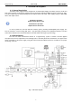
www.pulsar.pl EN54-3A28 RED POWER The connection of external devices to the EXT IN input is shown in the electrical diagram below. OC outputs (open collector) or relay outputs can be used as the source of the signal. Fig. 12. Examples of connections. In the option with external switch, the V EXT jumper, which polarises the EXT IN input circuit and is required in such configuration, must be on.
www.pulsar.pl EN54-3A28 RED POWER 6.7. Increasing the number of outputs with optional EN54-LB4 or EN54-LB8 fuse modules. The PSU has two independently protected outputs for connecting the AUX1 and AUX2 receivers. If the power supply unit is connected with more receivers, then it is recommended to secure each of them with independent fuse.
www.pulsar.pl EN54-3A28 RED POWER 6.9. PSU overload. The PSU is fitted with the LED OVL (overload) on the PCB and indicator on the LED panel, informing about output overload. If the nominal current of the PSU is exceeded, the led turns on and the microprocessor starts a specially implemented procedure. Depending on time and overload level, microprocessor may disconnect the AUX1 and AUX2 outputs and switch into the battery-assisted operation. Restart will occur after 1 minute.
www.pulsar.pl EN54-3A28 RED POWER 7. Reserve power supply circuit. The PSU is fitted with intelligent circuits: battery charging circuit with the function of the accelerated charging and battery control, which main task is to monitor the condition of the batteries and the connections in the circuit. If the controller detects a power failure in the battery circuit, appropriate indication and activation of the APS FLT and ALARM technical outputs takes place. 7.1. Battery detection.
www.pulsar.pl EN54-3A28 RED POWER 7.6. Measurement of the resistance of the battery circuit. The PSU is checking the resistance in the battery circuit. During the measurement, the PSU driver takes into account the key parameters in the circuit, and once the limit value of 300m ohms is exceeded, a failure is indicated . A failure may indicate considerable wear or loose cables connecting the batteries. 7.7. Battery temperature measurement.
www.pulsar.pl EN54-3A28 RED POWER 8. Remote monitoring (options: Wi-Fi, Ethernet, RS485, USB). The PSU has been adjusted to operate in a system that requires a remote control of the parameters in a monitoring centre. Transmitting data concerning PSU status is possible due to an additional, external communication module responsible for communication in Wi-Fi, Ethernet or RS485 standard. The USB –TTL interface enables the connection between the PSU and the computer.
www.pulsar.pl EN54-3A28 RED POWER The RS485-WiFi „INTRE” interface is a device used to convert signals between the RS485 bus and the WiFi network. For proper operation, the unit requires an external power supply in the range of 10÷30V DC e.g. drawn from a PSU of the EN54 series. The unit is mounted in a hermetic enclosure protecting against adverse environmental conditions. Fig. 17. Ethernet network communication using the RS485 „INTRE” interface. 8.3. The Wi-Fi wireless communication.
www.pulsar.pl EN54-3A28 RED POWER The RS485-WiFi „INTRW” interface is a device used to convert signals between the RS485 bus and the WiFi network. For proper operation, the unit requires an external power supply in the range of 10÷30V DC e.g. drawn from a PSU of the EN54 series. The physical connection of the interface takes place under galvanic isolation. The unit is mounted in a hermetic enclosure protecting against adverse environmental conditions. Fig. 19.
www.pulsar.pl EN54-3A28 RED POWER 8.5. „PowerSecurity” program. The ”Power Security” program is available on www.pulsar.pl Its detailed description can be found in the manual. „Power Security” is a free computer program developed to view and analyze the information sent from the PSU installation spots. The main panel is presented below. Fig. 21. „Power security” main panel. It is possible to divide the main panel of the program into smaller areas, depending on the number of monitored power supplies.
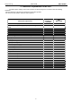
www.pulsar.pl EN54-3A28 RED POWER 9. Technical parameters. Electrical parameters (Table 12). Mechanical parameters (Table 13). Safety of use (Table 14). Recommended types and sections of installation cables (Table 15) Table 12. Electrical parameters.
www.pulsar.
www.pulsar.pl EN54-3A28 RED POWER 10. Technical inspections and maintenance. Technical inspections and maintenance can be performed after disconnecting the power supply from the power network. The PSU does not require any specific maintenance, however, its interior should be cleaned with compressed air if it is used in dusty conditions. In case of fuse replacement, use only compatible replacement parts. Technical inspections should be carried out not less frequently than once per year.
www.pulsar.
www.pulsar.pl EN54-3A28 RED POWER WEEE MARK According to the EU WEE Directive – It is required not to dispose of electric or electronic waste as unsorted municipal waste and to collect such WEEE separately. CAUTION! The power supply unit is adapted for cooperation with the sealed lead-acid batteries (SLA). After the operation period they must not be thrown but recycled according to the applicable law GENERAL WARRANTY CONDITIONS 1. Pulsar K. Bogusz Sp.j.