
Operating instructions
www.pulsar.pl EN54-3A28 RED POWER
27
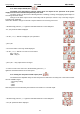
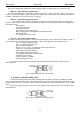
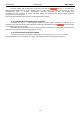
The connection of external devices to the EXT IN input is shown in the electrical diagram below. OC
outputs (open collector) or relay outputs can be used as the source of the signal.
Fig. 12. Examples of connections.
In the option with external switch, the V EXT jumper, which polarises the EXT IN input circuit and
is required in such configuration, must be on.
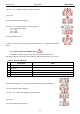
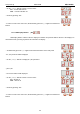
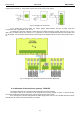
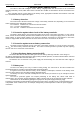
The EXTi input has been adjusted to work with fuse modules generating a failure signal in case of a fuse
fault in any of output sections (see section 6.7). To guarantee a correct cooperation between the fuse module and
the EXTi input, the connections shall be made as presented in the diagram below and the V EXT jumper must be
on.
Fig. 13. Example of a connection with the fuse module EN54-LB8.
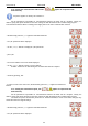
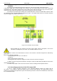
6.6. Indication of the enclosure opening - TAMPER.
The PSU is fitted with the microswitch tamper indicating enclosure opening.
The tamper cable is not connected to the terminal in the factory settings. In order to activate tamper,
remove the jumper from tamper terminal (Fig. 2 [12]) and plug in the tamper cable.
Each opening the enclosure will generate a failure signal at the PSU FLT and ALARM technical outputs
and will save the event in the internal memory of the PSU.