
Operating instructions

www.pulsar.pl EN54-3A28 RED POWER
28
6.7. Increasing the number of outputs with optional EN54-LB4 or EN54-LB8 fuse
modules.
The PSU has two independently protected outputs for connecting the AUX1 and AUX2 receivers.
If the power supply unit is connected with more receivers, then it is recommended to secure each of them with
independent fuse. This solution will protect the power supply system, while the damage to only one receiver (short-
circuit on the line) could cause damage to other receivers connected to the same output.
The solution is provided by the optional fuse module EN54-LB4, 4-channel or EN54-LB8, 8-channel, while
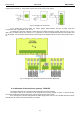
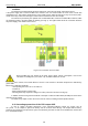
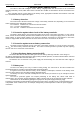
its mounting location is provided within the housing (see Fig. 4). The figure below shows the connection between
the power supply, fuse module and receivers.
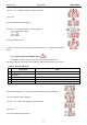
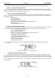
Fig.14. The connection of fuse module
When installing the fuse module in the PSU, power supply current consumption, used for the
calculation of standby time (see section 7.8), should be taken into account.
Depending on the version, fuse module allows to connect 4 or 8 receivers to the PSU. Output state is indicated by
green LEDs.
Blown fuse is indicated as follows:
- corresponding LED turns off: L1 for AUX1 etc.
- red LED on
- PSU technical output on (Hi-Z state)
- switching PSU relay output into voltage free status (contacts as shown in the Fig.14).
In addition, blown fuse signal is transmitted to the input of collective failure EXTi (ALARM) and saved in the
internal memory of PSU.
The PSU’s relay output can also be used for remote control, including external optical indication.
6.8. Overvoltage protection of the PSU output OVP.
In case of voltage exceeding 30,5V±0.5V at the switching regulator’s output, the system cuts off
the power at the outputs to protect the battery and the receivers from damage. The outputs will be battery-
powered. The activation of the protection system is indicated by the OVP red LED on the PCB board, and the PSU
FLT and ALARM outputs.