
User Instructions


www.pulsar.pl EN54C RED POWER plus
16
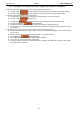
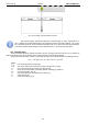
5.4. Indication of the enclosure opening - TAMPER.
The PSU is fitted with the microswitch tamper indicating enclosure opening.
The tamper cable is not connected to the terminal in the factory settings. In order to activate tamper,
remove the jumper from tamper terminal and plug in the tamper cable.
Each opening the enclosure will generate a failure signal at the ALARM technical output.
Fig. 12. TAMPER technical output.
5.5. PSU overload.
If the output overload occurs during the PSU operation, the PSU will limit the battery charging current for
1 minute. If, after this time, the overload is removed, the normal charging mode will be restored.
5.6. Short-circuit of the PSU output.
In case of short-circuit of the AUX1 or AUX2 output, one of the fuses - F
AUX1
or F
AUX2
– becomes
permanently blown. The restoration of the voltage at the output requires the replacement of the fuse.
During a short circuit, the PSU failure is indicated by the ALARM LED and a collective failure signal at the
ALARM output.
5.7. Additional modules.
The PSU can be used with optional fuse or sequential modules that will increase its functionality in the case
of extended fire protection systems. A place to mount additional modules has been provided inside the power
supply housing.
When installing the fuse module in the power supply, take into account the current consumption for
the power supply's own needs, which is used for the calculation of the standby time (see section 6.8).
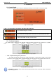
5.7.1. Extending the number of PSU outputs - EN54C-LB4 and EN54C-LB8 fuse modules.
The PSU is fitted with two independently protected outputs for connecting AUX1 and AUX2 receivers.
If more receivers are connected to the power supply, it is recommended to secure each of them with an
independent fuse. Such a solution will allow avoiding the failure of the entire system in the event of a fault (short
circuit on the line) of any of the connected receivers.
The possibility of such protection is provided by the optional EN54C-LB4 (4-channel) or EN54C-LB8
(8-channel) fuse module, for which the mounting location is provided inside the housing (Fig. 3).
Figure 10 shows the connection of the power supply, the fuse module, and the receivers (LOAD).
The fuse module, depending on the version, allows connecting 4 or 8 receivers to the power supply.
Output state is indicated by green LEDs.
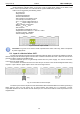
The blown strip fuse is signaled as follows:
- switching off the appropriate LED: L1 for AUX1 etc.
- the red PSU LED lights up
- switching the PSU relay output into a no-voltage state (contacts as in Figure 11)
In addition, the blown fuse signal is passed to the EXTi input of the collective power supply failure, and the PSU
reports a failure at the ALARM output.
The relay output of the PSU fuse strip can be used for remote control, e.g. external optical indication.